Cutting and making melded arrays

Helpful hints on how to build 'em, and where to get the stuff you need.
Message
Author
User avatar
DAVID_L_PERRY
Posts: 1685
Joined: Mon Jul 10, 2006 7:35 am
Location: UK North west
Contact:

Cutting and making melded arrays

#1 Post by DAVID_L_PERRY »

I have just done a couple of 6bank melded arrays for a fellow UK builder for a pair of wedghorns, and a 10 bank melded array for my new omni 10 so thought I would photograph the process that I use, which is slightly different than shown in the plans, only in as much as I don't cut the 45deg angle on individual piezo's but cut them on the entire bank, which results in one continuous alligned cut.

As always, others will have their own methods that work for them, just thought I would show you the one that has worked very well for me.

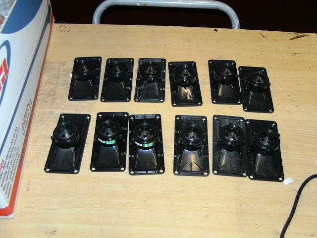
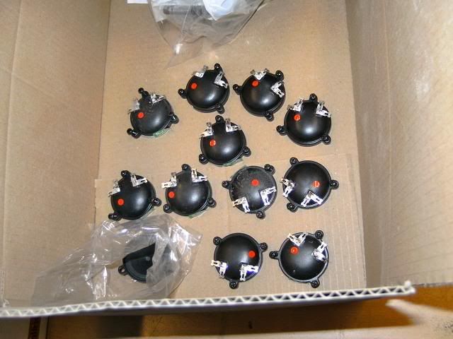
Step one remove the elements !!!!

Image

Image

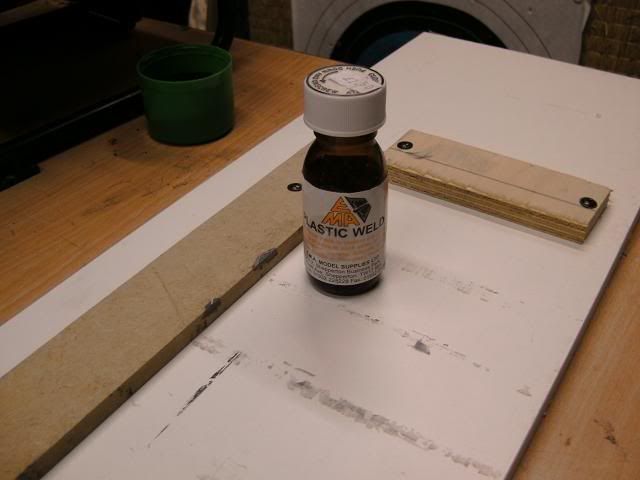
Step 2 cut them all to width and glue each full side up:-

Image

I now use 'plastic weld' model cement, rather than the thick ABS cement. It is very thin consistency, cures in minutes, and will work its way into joins using capillary action.

Image

If the piezo is going to be exposed I would quickly run the flat arrays over some sandpapar to smooth them out at this point, as its simpler than when they are joined at 45deg.

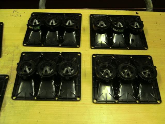
Step 3 cut each side in one pass at 45deg on a fine tooth table saw so you get a single smooth cut on each side and glue both side together (rather than lots of individual piezo's to cut and glue separately)

Image

If your arrays are to remain exposed I would sand the joints down a little, and then spray the dront of the array with a satin black spray paint (car body primer spray works well for this I have found)

Step 4 re-attach the elements and we are done:-

Image

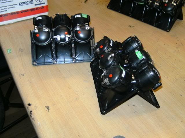
As Richard is mounting them the same way I did on my wedghorn alternate elements can be rotated through 180deg staggered as shown to make cutting and mounting closer simpler as you don't have to cut through the element screw housing.

Image

Some builds require the element lugs all to be pointing inside, rather than alternated as space is tight, so adjust to suit.

Hope this is of some benefit to others
Dave

User avatar
Scott Brochu
Posts: 2473
Joined: Sat Mar 10, 2007 11:53 pm
Location: Maine
Contact:

#2 Post by Scott Brochu »

Yes, David this will help a lot when I do my 200's thanks.
Great idea about cutting them all at the same time, this will cut down on time as your only making one cut at a 45 per side verses 16.

never thought of that :wink:
Drumming is a way of life.
ME LIKE TO HIT THINGS!
http://billfitzmaurice.info/forum/viewt ... 26&t=11232

User avatar
SoundInMotionDJ
Posts: 1750
Joined: Thu Mar 15, 2007 1:31 pm
Location: DFW, Texas
Contact:

#3 Post by SoundInMotionDJ »

I did the same thing...make a bank of 8 then cut the 45deg angle.

I'd only add one more thing to David's list...sand with 200 & 400 grit BEFORE you glue them into a "V". It is soooo much easier to sand a flat array.

--Stan Graves
10 T39S + 10 DR200 + 1 T48

User avatar
Tim A
Posts: 3663
Joined: Sat Jan 13, 2007 5:23 pm
Location: SE Michigan, Licensed BF Builder

#4 Post by Tim A »

That's how I do mine as well, and I believe G Dougherty posted about doing the 45 cut all at once. I 'think' it's easier, but since I've never done it the other way I can't be sure.

The comment about sanding is a good one. Once mine are glued up and before I cut the 45, the faces are sanded down and any voids filled with more cement (the black ABS stuff), then sanded again. The units will perch face up between two supports like the open jaws of a wood vice. Some 220 on an RO sander makes quick work and a nice satiny finish. Once sanded they look like a single continuous unit.

User avatar
DAVID_L_PERRY
Posts: 1685
Joined: Mon Jul 10, 2006 7:35 am
Location: UK North west
Contact:

#5 Post by DAVID_L_PERRY »

SoundInMotionDJ wrote: I'd only add one more thing to David's list...sand with 200 & 400 grit BEFORE you glue them into a "V"....
Pretty much as I said in the first post then....... :D
If the piezo is going to be exposed I would quickly run the flat arrays over some sandpapar to smooth them out at this point, as its simpler than when they are joined at 45deg.

User avatar
SoundInMotionDJ
Posts: 1750
Joined: Thu Mar 15, 2007 1:31 pm
Location: DFW, Texas
Contact:

#6 Post by SoundInMotionDJ »

DAVID_L_PERRY wrote:
SoundInMotionDJ wrote: I'd only add one more thing to David's list...sand with 200 & 400 grit BEFORE you glue them into a "V"....
Pretty much as I said in the first post then....... :D
If the piezo is going to be exposed I would quickly run the flat arrays over some sandpapar to smooth them out at this point, as its simpler than when they are joined at 45deg.
That's what I get for looking at all the pretty pictures and only skimming the text... Shame on me... :oops:

--Stan Graves
10 T39S + 10 DR200 + 1 T48

gdougherty
Posts: 2623
Joined: Sun Jan 28, 2007 11:13 am
Location: Denver, CO
Contact:

#7 Post by gdougherty »

Tim Ard wrote:That's how I do mine as well, and I believe G Dougherty posted about doing the 45 cut all at once. I 'think' it's easier, but since I've never done it the other way I can't be sure.
I know it's easier. I built mine without the need for a jig other than a flat surface with a raised edge like a circular saw guide to make sure the columns lined up straight before cutting the 45's. Using dipped MEK to glue the pair of 45's together I hand held for 20-30 seconds until it set up with no need for a jig. There's enough surface between the two to enforce the 45 degree angle without worry, just align the top and bottom. Did all the work on a sheet of wax paper. Ripping them against the fence on a table saw ensured that every horn was identical in size.

kesslari
Posts: 114
Joined: Wed Jan 30, 2008 5:36 pm

#8 Post by kesslari »

Dave, good tutorial here!

mlkras
Posts: 82
Joined: Tue Sep 12, 2006 11:51 am
Location: Boston, Massachusetts

Quick wiring tip for all array types

#9 Post by mlkras »

On the first Piezo array that I built I made up individual short stripped wire sections to solder together the individual tweeters. A couple of weeks later I had an Ah ha moment in the hardware store. I bought a roll of 20 gauge bare copper wire and when I wire up the tweeters I just thread the wire through each of the tweeters as shown in the schematic. A dab of solder on each contact with each tweeter and you are done. This is probably more mechanically stable and reliable than a bunch of point to point wiring.

So ok the wire is bare and represents somewhat of an electrical hazard but who ever sticks their hind in the enclosure without asking deserves what they get. You could always thread the wire through some shrink wrap between the tweeters.

horst
Posts: 648
Joined: Sat Aug 05, 2006 2:14 am
Location: Sydney, Australia

Re: Quick wiring tip for all array types

#10 Post by horst »

mlkras wrote:On the first Piezo array that I built I made up individual short stripped wire sections to solder together the individual tweeters. A couple of weeks later I had an Ah ha moment in the hardware store. I bought a roll of 20 gauge bare copper wire and when I wire up the tweeters I just thread the wire through each of the tweeters as shown in the schematic. A dab of solder on each contact with each tweeter and you are done. This is probably more mechanically stable and reliable than a bunch of point to point wiring.

So ok the wire is bare and represents somewhat of an electrical hazard but who ever sticks their hind in the enclosure without asking deserves what they get. You could always thread the wire through some shrink wrap between the tweeters.
you can use your method with insulated wire, it's really easy to strip the wire with one of these
Image
in the middle of the wire and exopse enough wire to solder to the terminal.

mlkras
Posts: 82
Joined: Tue Sep 12, 2006 11:51 am
Location: Boston, Massachusetts

Removing tweeter elements

#11 Post by mlkras »

When building tweeter arrays I have always put blue painters tape across the mouth of the tweeter horns to keep debris out of the horn throat while they are being cut and worked.

It also has seemed to be a good idea to remove the tweeter elements so that the vibration of the saw does not injure them although I have never done that. My concern has been that my piezos don't always seem to survive the removal and replacement of their elements. There appears to be a small hinge flap on one side of the piezo that needs to be cut for easy removal of the element. Any tips or thoughts here?

gdougherty
Posts: 2623
Joined: Sun Jan 28, 2007 11:13 am
Location: Denver, CO
Contact:

Re: Quick wiring tip for all array types

#12 Post by gdougherty »

horst wrote:
mlkras wrote:On the first Piezo array that I built I made up individual short stripped wire sections to solder together the individual tweeters. A couple of weeks later I had an Ah ha moment in the hardware store. I bought a roll of 20 gauge bare copper wire and when I wire up the tweeters I just thread the wire through each of the tweeters as shown in the schematic. A dab of solder on each contact with each tweeter and you are done. This is probably more mechanically stable and reliable than a bunch of point to point wiring.

So ok the wire is bare and represents somewhat of an electrical hazard but who ever sticks their hind in the enclosure without asking deserves what they get. You could always thread the wire through some shrink wrap between the tweeters.
you can use your method with insulated wire, it's really easy to strip the wire with one of these
Image
in the middle of the wire and exopse enough wire to solder to the terminal.
That might work if you were using something on the order of individual 24ga CAT5 strands. Lots of wire would be problematic with the thickness of the insulation threading through the tabs. I guess you could also just do a single wrap around the indentations in the side of the terminal and a touch of solder to hold from there.

User avatar
Frankenspeakers
Posts: 1089
Joined: Sat May 13, 2006 2:13 pm
Location: Fremont Ca

#13 Post by Frankenspeakers »

Heat Shrink tubing anyone? I use it all the time. If you use the low temp stuff, a hair drier will do.
There is no technical problem however complex, that cannot be solved or finessed by a direct application of brute strength and ignorance.

"Gimme the hammer... Naaaw not that one, the freakin' big one- I'll MAKE it fit!"

Mark Coward
Posts: 2601
Joined: Mon May 15, 2006 10:47 am
Location: Memphis, TN

Re: Quick wiring tip for all array types

#14 Post by Mark Coward »

gdougherty wrote:
horst wrote:
mlkras wrote:On the first Piezo array that I built I made up individual short stripped wire sections to solder together the individual tweeters. A couple of weeks later I had an Ah ha moment in the hardware store. I bought a roll of 20 gauge bare copper wire and when I wire up the tweeters I just thread the wire through each of the tweeters as shown in the schematic. A dab of solder on each contact with each tweeter and you are done. This is probably more mechanically stable and reliable than a bunch of point to point wiring.

So ok the wire is bare and represents somewhat of an electrical hazard but who ever sticks their hind in the enclosure without asking deserves what they get. You could always thread the wire through some shrink wrap between the tweeters.
you can use your method with insulated wire, it's really easy to strip the wire with one of these
Image
in the middle of the wire and exopse enough wire to solder to the terminal.
That might work if you were using something on the order of individual 24ga CAT5 strands. Lots of wire would be problematic with the thickness of the insulation threading through the tabs. I guess you could also just do a single wrap around the indentations in the side of the terminal and a touch of solder to hold from there.
You wouldn't have to thread it through, just solder it on top.
Mark Coward

mlkras
Posts: 82
Joined: Tue Sep 12, 2006 11:51 am
Location: Boston, Massachusetts

Taking apart peizos

#15 Post by mlkras »

Any advice on taking apart piezos so that they still work when you reassemble them?

Post Reply