OP, your straight bit with top roller bearing ties into a question I have running in TIPS.
1st Q: Is your bit a one-piece unit, or do you have to fiddle with assembling it, etc?
2nd Q: Do you make your cuts in a single plunge, or multiple passes?
If a single plunge, do you find this is hard on the bit?
Pictures of TLAH Build - Making some progress...
-
bgavin
- Posts: 5738
- Joined: Thu May 04, 2006 10:58 am
- Location: Sacramento, Moderator/Licensed BF Builder
- Contact:
Re: Pictures of TLAH Build - Making some progress...
My biggest worry is that when I'm dead and gone, my wife will sell my toys for what I said I paid for them.
-
Pixelmaster
- Posts: 117
- Joined: Fri Mar 21, 2008 11:09 pm
- Location: Atlanta
- Contact:
Re: Pictures of TLAH Build - Making some progress...
Great questions.
1) The bit is a standard router bit with built in pilot so there is no messing around with assembling / disassembling the bit itself. You can take a look at these at Lowe's or HD.
2) After I layout my opening on my workpiece, I simply drill a hole and then use a saber saw to rough out the opening so that I remove the bulk of the material from the opening. Then I place my template in place, secure it, and there is very little material to remove with the router which comes out in two or three quick passes around the template. This approach will also prolong the life of your router bit because you are removing far less material with your bit.
You could plunge cut your way into the opening but that would require more work with the router than it is worth. That would not be my approach unless (in a different situation) the opening was smaller and cutting the waste material out with a saber saw turns out to be a waste of time because the opening is so small in the first place.
Hope that helps!
Lee
Re: Pictures of TLAH Build - Making some progress...
A thing of beauty. Phil
DR 250's #2
T39's 14 in with 102 #2
T39's 14 in with 102 #2
-
Pixelmaster
- Posts: 117
- Joined: Fri Mar 21, 2008 11:09 pm
- Location: Atlanta
- Contact:
Re: Pictures of TLAH Build - Making some progress...
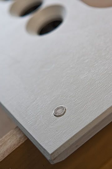
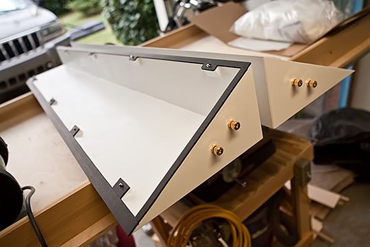
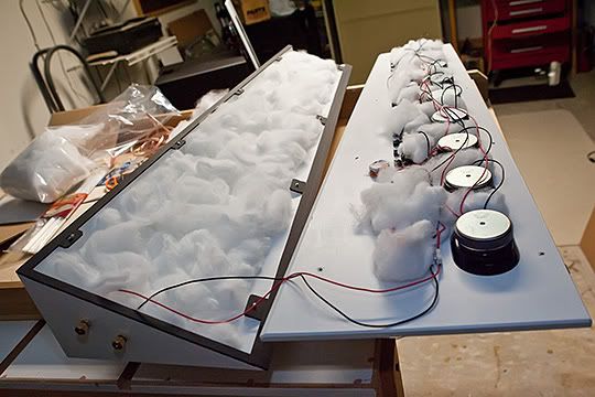
Finally completed the front grille with 1 inch standoffs in all four corners. I embedded a small magnet in each standoff and also in the front baffle. If you do this make sure you have the polarity of the magnets aligned before your set them permanently. I drilled the holes for the magnets slightly oversized and just a little shallow so that they stand just above the front surface of the baffle. I set them with bondo after grinding a slight groove all the way around the magnet so that once set in the bondo the magnet could not get "sucked" out of the hole it was set in. (These little magnets are on closeout from PE and they are strong little devils).
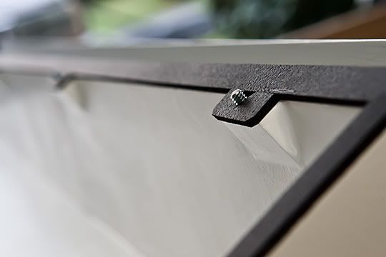
Another view...
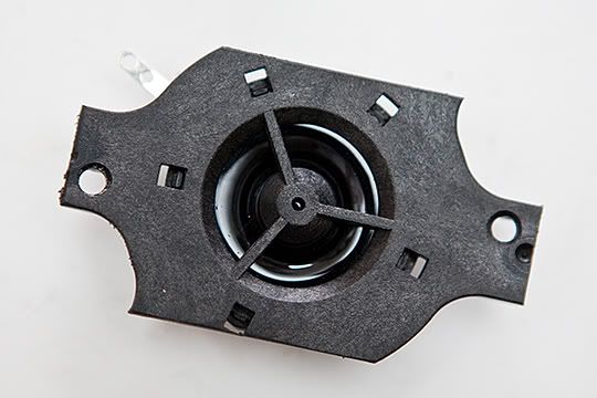
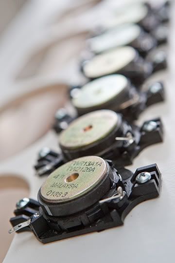
As I stated earlier I decided to leave a small portion of the original 6X9 frame in place and use it for securing the tweeters to the inside surface of the baffle. If anyone is interested I can get some pictures together of the fixture I built for cutting the 6X9's away so that each driver is identical. Here is what's left after I cut the excess away.
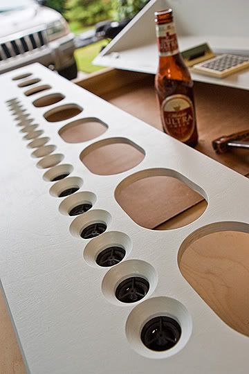
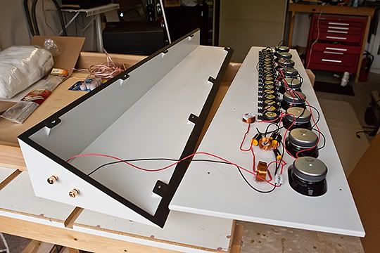
Getting close to mounting the drivers. The only bad thing about this build is the simple fact that so many drivers are used that some of the routines you go through as you continue your build get pretty redundant....
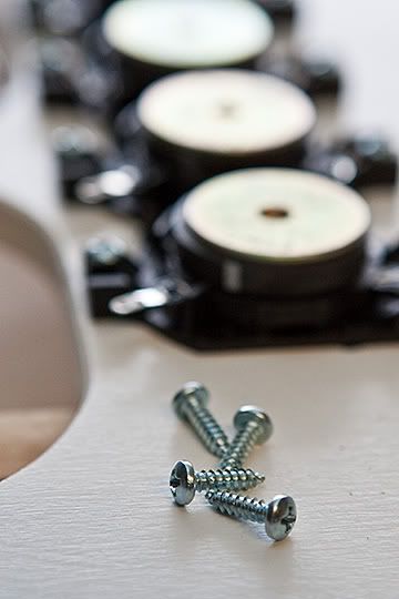
I'm screwing the tweeters in with #6 X 1/2 inch sheet metal screws being careful not to drill my pilot holes all the way through my finished front baffle. I place a very (very) small amount of black DAP Dynaflex 230 sealant to the front surface of the tweeters before I screw them down to insure I have a nice tight seal without getting any squeeze out inside the hole on the front...
Mounted...
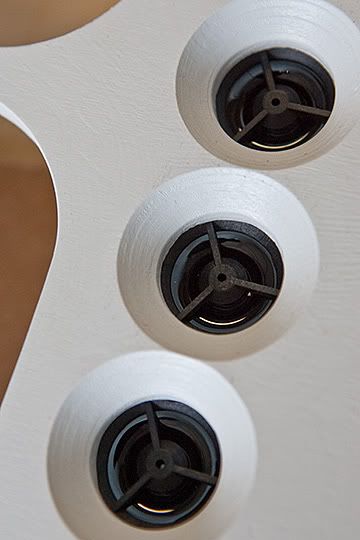
Here is what they are looking like from the front. I'd have to say I love the black & white contrast. Starting to get a bit excited that as I'm coming down the homestretch here...
Time for a little refreshment.
BTW - I tried to test the tweeters using the approach listed with Pink Noise and an iPod and I could not get any of my drivers (tweeters or mid-basses) to sound off at all. I tried different volume levels with my iPod and I tried different wire configurations (as there are four wires inside the cutoff headphone wire) and couldn't get anything to make a sound. If anyone has any suggestions please let me know. I decided to forge ahead and start mounting drivers hoping that they are all good.
Another view...
As I stated earlier I decided to leave a small portion of the original 6X9 frame in place and use it for securing the tweeters to the inside surface of the baffle. If anyone is interested I can get some pictures together of the fixture I built for cutting the 6X9's away so that each driver is identical. Here is what's left after I cut the excess away.
Getting close to mounting the drivers. The only bad thing about this build is the simple fact that so many drivers are used that some of the routines you go through as you continue your build get pretty redundant....
I'm screwing the tweeters in with #6 X 1/2 inch sheet metal screws being careful not to drill my pilot holes all the way through my finished front baffle. I place a very (very) small amount of black DAP Dynaflex 230 sealant to the front surface of the tweeters before I screw them down to insure I have a nice tight seal without getting any squeeze out inside the hole on the front...
Mounted...
Here is what they are looking like from the front. I'd have to say I love the black & white contrast. Starting to get a bit excited that as I'm coming down the homestretch here...
Time for a little refreshment.
BTW - I tried to test the tweeters using the approach listed with Pink Noise and an iPod and I could not get any of my drivers (tweeters or mid-basses) to sound off at all. I tried different volume levels with my iPod and I tried different wire configurations (as there are four wires inside the cutoff headphone wire) and couldn't get anything to make a sound. If anyone has any suggestions please let me know. I decided to forge ahead and start mounting drivers hoping that they are all good.
Re: Pictures of TLAH Build - Making some progress...
Beautiful work!
Thank you!
I would love to know. I am getting ready to start the same project. Also can you share how you created the 3x5 template. It looks perfect.If anyone is interested I can get some pictures together of the fixture I built for cutting the 6X9's away so that each driver is identical.
Thank you!
Re: Pictures of TLAH Build - Making some progress...
Pixelmaster wrote: BTW - I tried to test the tweeters using the approach listed with Pink Noise and an iPod and I could not get any of my drivers (tweeters or mid-basses) to sound off at all. I tried different volume levels with my iPod and I tried different wire configurations (as there are four wires inside the cutoff headphone wire) and couldn't get anything to make a sound. If anyone has any suggestions please let me know. I decided to forge ahead and start mounting drivers hoping that they are all good.
You certainly should be getting a sound out of them, you may not be making any contact, those headphone cords can be really tough things and stripping the ends can be really tricky, especially because the wire is so thin and there are so many starns often intertwined with some fibre, try tinning the ends with lots of heat to burn through the laquer
-
Pixelmaster
- Posts: 117
- Joined: Fri Mar 21, 2008 11:09 pm
- Location: Atlanta
- Contact:
Re: Pictures of TLAH Build - Making some progress...
I went with a 1/8" mono jack and wired it up with two alligator clips on the ends of my leads. Once I got it set up this way the iPod worked great for testing.
All 54 drivers sounded off just fine.
(I had to get away from trying to use the leftover stereo jacks with attached headphone wire - this approach never produced a sound).
L.
All 54 drivers sounded off just fine.
(I had to get away from trying to use the leftover stereo jacks with attached headphone wire - this approach never produced a sound).
L.
-
Pixelmaster
- Posts: 117
- Joined: Fri Mar 21, 2008 11:09 pm
- Location: Atlanta
- Contact:
Re: Pictures of TLAH Build - Making some progress...
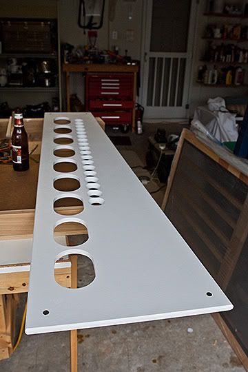
The 3X5 template was pretty easy to make and it is a HUGE time saver.
The first thing I did was measure the back side of the driver at the level of the gasket so that I could determine the exact length and width of the metal speaker frame. Then I added 1/16 of an inch to that dimension (both length and width) so that I would have 1/32 of an inch clearance all the way around when complete. This turned out to be just perfect and the speakers almost self-center themselves in the openings when you drop them in...there is just enough play and no need for sealant as the speaker gasket does the job.
I would recommend that when you lay out your opening on the material you choose for your template (I used a scrap of 1/2 inch baltic birch) that you either use a very sharp pencil for a fine line or better yet, cut your lines in with a knife and a set of dividers. If your cut your lines in and they are accurate then you can just "split" the line as you finish the opening and you are there!
After the opening is laid out on your material then just cut the excess material out with a saber saw so you have maybe a 1/16 to an 1/8 of an inch of material left to remove. I bought a little drum sander attachment (from Lowe's) which is really intended to be used in a handheld drill. Instead of using a hand held drill, I put it in a small drillpress that I'm borrowing from my brother-in-law and used it like a make-shift spindle sander. This works great to remove the excess material left from the saber saw and you can gradually work it down till the knife line splits and you are finished with a very nice template to work with.
There are always a million different ways to get from point A to point B but that's what I did. Hope that helps!
Re: Pictures of TLAH Build - Making some progress...
Thanks for the info on creating the router template. I am going to try it.
-
Pixelmaster
- Posts: 117
- Joined: Fri Mar 21, 2008 11:09 pm
- Location: Atlanta
- Contact:
Re: Pictures of TLAH Build - Making some progress...
Here are a couple of images of the fixture I made for cutting my tweeter frames down on my table saw.
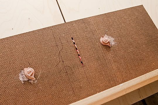

I used the panel jig as a platform for holding my fixture in place. The fixture is a piece of hardboard. I coated two of the mounting holes with a thin layer of vaseline as a parting agent and then squished bondo into the two holes and positioned it on the hardboard and let it set. After the bondo is set up then I just popped the frame off, trimmed the outside up so that I could pivot the edge off of the guide on the panel jig for plunge cutting the frames off. All the tweeter frames are exactly the same size so the "posts" that are made of bondo do a great job of holding each frame in place. The frame gets modified further to cut other two connections.
Here are the final images of the cabinets...
Up on the walls...
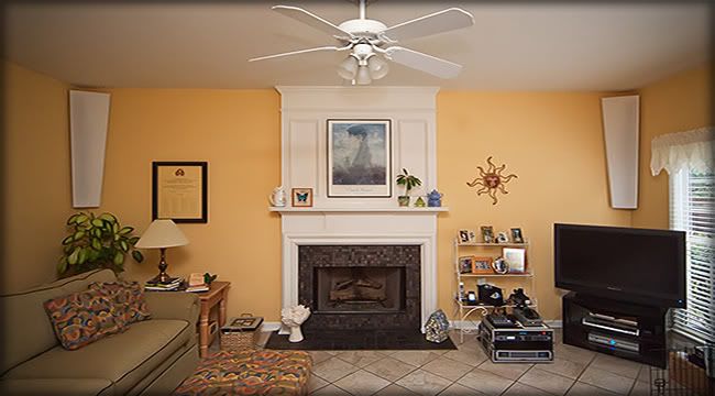
And fully exposed in all their glory...(The Full Monty)
I used the panel jig as a platform for holding my fixture in place. The fixture is a piece of hardboard. I coated two of the mounting holes with a thin layer of vaseline as a parting agent and then squished bondo into the two holes and positioned it on the hardboard and let it set. After the bondo is set up then I just popped the frame off, trimmed the outside up so that I could pivot the edge off of the guide on the panel jig for plunge cutting the frames off. All the tweeter frames are exactly the same size so the "posts" that are made of bondo do a great job of holding each frame in place. The frame gets modified further to cut other two connections.
Here are the final images of the cabinets...
Up on the walls...
And fully exposed in all their glory...(The Full Monty)
-
Scott Brochu

- Posts: 2473
- Joined: Sat Mar 10, 2007 11:53 pm
- Location: Maine
- Contact:
Re: Pictures of TLAH Build - Making some progress...
Man! Pixelmaster those look good. Especially the last one it's the money shot. 
did you end up making some rears and a center?
did you end up making some rears and a center?
Drumming is a way of life.
ME LIKE TO HIT THINGS!
http://billfitzmaurice.info/forum/viewt ... 26&t=11232
ME LIKE TO HIT THINGS!
http://billfitzmaurice.info/forum/viewt ... 26&t=11232
-
Pixelmaster
- Posts: 117
- Joined: Fri Mar 21, 2008 11:09 pm
- Location: Atlanta
- Contact:
Re: Pictures of TLAH Build - Making some progress...
Thanks Scott.
I've got this set up as a stereo rig for music listening only (for now)

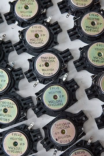
The sound from these speakers boggles my mind - to think that the individual drivers were so inexpensive ($0.55 per tweeter and $1.50 per mid-bass) totally blows me away. The stereo field projects well back behind where I was standing to take this pic, back into the kitchen which is behind me. They sound great!
Lee
I've got this set up as a stereo rig for music listening only (for now)
The sound from these speakers boggles my mind - to think that the individual drivers were so inexpensive ($0.55 per tweeter and $1.50 per mid-bass) totally blows me away. The stereo field projects well back behind where I was standing to take this pic, back into the kitchen which is behind me. They sound great!
Lee
-
Pixelmaster
- Posts: 117
- Joined: Fri Mar 21, 2008 11:09 pm
- Location: Atlanta
- Contact:
Re: Pictures of TLAH Build - Making some progress...
I thought I would add just one more comment here after living with my new TLAH's for about a week or so...
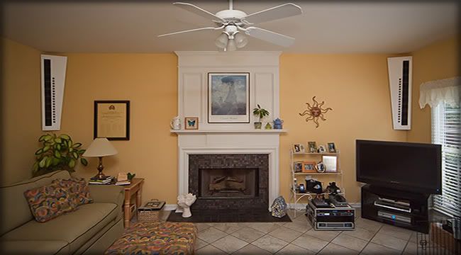
Take it very seriously that the vertical zone of disbursement on the tweeters is limited. The horizontal zone of disbursement is great but if your ears aren't in the zone then the highs will disappear very quickly.
Because of this and because of the long throw I have in the space my speakers are located in I decided to create a speaker mount that allows me to aim the speakers into one of two listening areas.
Mounted normally they are aimed deep into the space so that the sweet spot is in my dining and kitchen area further back. The other area that I want to listen in is closer to the speakers and lower; in my favorite chair. I could not cover all areas I wanted so I created this mount. It consists of a 6 inch heavy duty strap hinge (like the type used on a gate on a fence. The bottom of each speaker is hinged to the wall. The top has a cable that allows me to tilt the top of the cabinet into the immediate room (where my favorite chair is located) but the cable limits the amount it can tilt on the hinge. The cable is attached to the back of the speaker and then to an eye bolt that is set into the wall behind the cabinet. I can tilt the cabinet back into a fully vertical position and I've used 4 magnets that snap the top back up tight to the wall. All the weight bearing is taking place where the hinge attaches the cabinet to the wall.
Most of the time the cabinets are snapped up tight to the wall but when I want to sit with a beer and relax I can aim them straight into my favorite spot where I like to sit and listen.
Works great.
Thought I would share the idea for what it's worth.
Cheers!
L.

Re: Pictures of TLAH Build - Making some progress...
Fantastic idea. I wondered about the tweeters shooting over your head while you sit to watch TV when I saw the pics. I see the design television shows mounting new flatscreen TVs over the fireplace and think, that's great if you're standing, but who wants to relax watching something above their heads when they're sitting?
AudioFlyer DJ: DR200 & Titan39/Titan48
BASS: Combo Amp & Titan39
BASS: Combo Amp & Titan39
-
Bill Fitzmaurice

- Site Admin
- Posts: 29127
- Joined: Tue May 02, 2006 5:59 pm
Re: Pictures of TLAH Build - Making some progress...
My 42" wouldn't fit into my entertainment center, so it's on top of it, with the screen center about 6 feet above the floor. It's considerably more comfortable to watch than my old 32" CRT was on a shelf some 30 inches lower.Gauss wrote: I see the design television shows mounting new flatscreen TVs over the fireplace and think, that's great if you're standing, but who wants to relax watching something above their heads when they're sitting?