Some RTA plots for OT15

EQ guys are using on their cabs/systems. A good starting place if you don't have your own RTA.
Message
Author
jeffbabcock

Re: Some RTA plots for OT15

#16 Post by jeffbabcock »

Bill Fitzmaurice wrote:
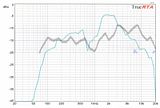
The huge bump around 1.5kHz is the result of the very high sensitivity of the BMS, while the severe roll off above that 'plateau' is typical of CD horns, which trade off flat axial response for wide dispersion.
True, however something is not right.
The amount of variation in horn response seems too high. Perhaps the P-Audio horn used is not a good candidate.

Are these boxes biamped? Regardless, what are the crossover specs? Perhaps inadequate slopes are accounting for the huge bump in terms of allowing combined output from both the LF and HF drivers.

Here's what you should be seeing in terms of raw HF performance on a 90x75 horn:
http://bmsspeakers.com/fileadmin/bms-da ... curves.jpg

Certainly the typical CD/horn roll off is expected, but not to the extent in the measurements taken. I've measured many good HF drivers and they usually look smoother than this even unprocessed. It is expected that you need to EQ the CD, but this seems extreme, suggesting either contribution of the LF driver in the measurement due to crossover inadequacy, or the PAudio horn not being ideal.
User avatar
DJPhatman
Posts: 5411
Joined: Mon Aug 14, 2006 5:08 am
Location: Warren, MI
Contact:

Re: Some RTA plots for OT15

#17 Post by DJPhatman »

jeffbabcock wrote:or the PAudio horn not being ideal.
Ding! Ding! Ding! We 'ave a Winner!!


Sorry, my smart-a$$ side takes over and I just can't help it.
I know money often seals the deal, but seriously, quality is an investment, not an expense... Grant Bunter
Accept the fact that airtight and well-braced are more important than pretty on the inside. Bill Fitzmaurice

WB
Posts: 1745
Joined: Sat May 13, 2006 3:06 pm
Location: Ontario. Yours To Discover

Re: Some RTA plots for OT15

#18 Post by WB »

Strapping Young Stu wrote: Image
Couldn't the 1.5-3K Hz bump be the result of the ground plane measurement giving the HF a 6 dB bump because it's in quarter space? Might look very differently when measured in full space (which is really half space for the HF). That's why Bill combines the full space and half space measurements. I know whenever I've measured a cab ground plane, it usually yields ugly HF results.
Tomorrow I'm going to stop procrastinating - WB

User avatar
Bill Fitzmaurice
Site Admin
Posts: 28916
Joined: Tue May 02, 2006 5:59 pm

Re: Some RTA plots for OT15

#19 Post by Bill Fitzmaurice »

WB wrote: Couldn't the 1.5-3K Hz bump be the result of the ground plane measurement giving the HF a 6 dB bump because it's in quarter space? .
It could indeed. That's why the preferred testing method is to take a groundplane from at least 2 meters for the low end, then put the cab on the ground facing upward with the mic suspended at least 2 meters above it to get the halfspace reading above the baffle step, and then combine the two for a true half-space reading. OTOH for an in-use RTA measure it in use, in the room, the mic in the audience.

Gregory East
Posts: 3495
Joined: Sat May 13, 2006 9:56 pm

Re: Some RTA plots for OT15

#20 Post by Gregory East »

Ok, relative newbie question time. Why does the HF get a bump in quarterspace?

WB
Posts: 1745
Joined: Sat May 13, 2006 3:06 pm
Location: Ontario. Yours To Discover

Re: Some RTA plots for OT15

#21 Post by WB »

Gregory East wrote:Ok, relative newbie question time. Why does the HF get a bump in quarterspace?
The short wave lengths of the higher frequencies see the baffle as a boundary, whereas the lower frequencies (longer wave lengths) do not.
Tomorrow I'm going to stop procrastinating - WB

User avatar
Bill Fitzmaurice
Site Admin
Posts: 28916
Joined: Tue May 02, 2006 5:59 pm

Re: Some RTA plots for OT15

#22 Post by Bill Fitzmaurice »

WB wrote:
Gregory East wrote:Ok, relative newbie question time. Why does the HF get a bump in quarterspace?
The short wave lengths of the higher frequencies see the baffle as a boundary
So does the woofer horn. Once the mouth is a wavelength across radiation goes to hemispherical and the cab is in half-space even when suspended; with a 22" wide mouth that occurs around 600 Hz.

moo
Posts: 134
Joined: Thu Jan 31, 2008 11:38 am
Location: Dorset UK

Re: Some RTA plots for OT15

#23 Post by moo »

The HF horn is at the Top of the cab. The cab was upside down when I measured it to avoid cancellations from ground reflections in the HF.
So yes, jeff is right that the HF section is effectively measured in quarter space, and its output is higher than it will be when mounted on a pole.
This is not something that occurred to me at the time. :oops:

The HF horn is not a CD horn BTW. You do not get those lovely parallel lines in the angled plots from CD horns. When this cab is EQed flat on axis, it will also be flat off axis, but at a lower amplitude, because the angled plots are almost parallel to the on axis plots. Having an EQ that remains constant at all listening angles sound much better than CD horns which try to maintain the same amplitude at all angles.
Typical CD horns boost the response off axis by diffraction, but you end up with plots that go up and down at various frequencies at different angles. This means you can only achieve a good E.Q. at one angle only, the rest of the angles all have random peaks and troughs. This horn sounds much better than a CD horn off axis because of that.

The first single line trace is a calculated average of the measurements from 0-40 degrees. I thought this average would give Stuart a good starting point to eq for a flat-ish response throughout a typical room, but it will not match on axis measurements from the manufacturers.

So note to Stuart: The trace should therefore be interpreted as 6db to high in the 1-3 khz area.
If you want to bring a cab round sometime, I am willing to re-measure using Bills method for the HF.

Moo.
Last edited by moo on Thu Apr 22, 2010 4:34 pm, edited 1 time in total.
I live the smell of birch ply in the mornings... Smells like... Victory!

User avatar
Bill Fitzmaurice
Site Admin
Posts: 28916
Joined: Tue May 02, 2006 5:59 pm

Re: Some RTA plots for OT15

#24 Post by Bill Fitzmaurice »

moo wrote: If you want to bring a cab round sometime, I can re-measure the HF using Bills method.

Moo.
Be aware when you do so with the cab facing upward there will be a major notch at the Allison Effect frequency, but that's below the baffle step, so where that occurs you should be using the ground plane result anyway. And if the HF horn isn't coincidentally mounted even measuring at 2 meters won't be adequate for total wavefront integration of the two sources.

moo
Posts: 134
Joined: Thu Jan 31, 2008 11:38 am
Location: Dorset UK

Re: Some RTA plots for OT15

#25 Post by moo »

jeffbabcock wrote: Perhaps the P-Audio horn used is not a good candidate.
Here's what you should be seeing in terms of raw HF performance on a 90x75 horn:
http://bmsspeakers.com/fileadmin/bms-da ... curves.jpg

Certainly the typical CD/horn roll off is expected, but not to the extent in the measurements taken. I've measured many good HF drivers and they usually look smoother than this even unprocessed. It is expected that you need to EQ the CD, but this seems extreme, suggesting either contribution of the LF driver in the measurement due to crossover inadequacy, or the PAudio horn not being ideal.
Heres the Horn plot from the P-Audio site:
Attachments
Picture 1.png
I live the smell of birch ply in the mornings... Smells like... Victory!

User avatar
AntonZ
Posts: 2687
Joined: Sun May 14, 2006 6:00 am
Location: NL

Re: Some RTA plots for OT15

#26 Post by AntonZ »

Stu, do take time to add some more and thicker foam damping to the inner surfaces in your OT15's. I've added quite a bit inside two of the OT12's. It made a significant difference. They're getting sweeter every time I use them.

moo
Posts: 134
Joined: Thu Jan 31, 2008 11:38 am
Location: Dorset UK

Re: Some RTA plots for OT15

#27 Post by moo »

AntonZ wrote:Stu, do take time to add some more and thicker foam damping to the inner surfaces in your OT15's. I've added quite a bit inside two of the OT12's. It made a significant difference. They're getting sweeter every time I use them.
You seem to be presuming that Stus OT15s are constructed by the same builder as his OT12s - they are not.
These OT15s are built and finished to a higher standard than Stus OT12s were, which I had a look at before you bought them. I also noticed that the braces for the back doors of your OT12s have been missed by the builder. This may also make a small improvement to your OT12s if you put them in.

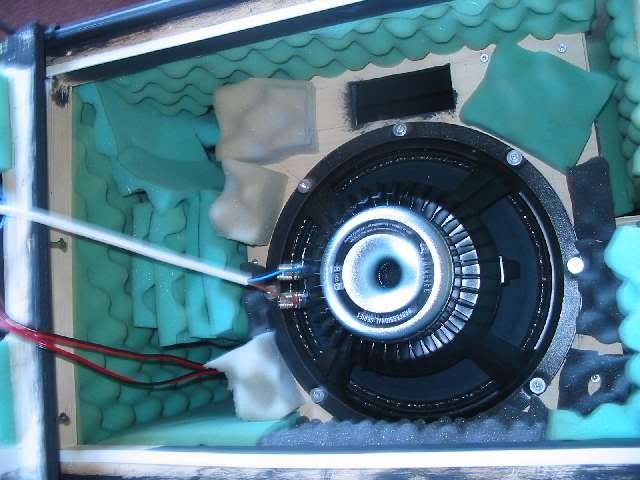
I lined the woofer chamber of Stu's OT15s with 2 1/2 inch (65mm) deep convoluted acoustic foam of the type sold for lining studio walls. I got a cheap deal from a supplier here in the U.K. The bonus is that this foam is also fire retardant to British Standards Specifications, so will not create a disaster if the crossover gets 'warm'.
The sharp eyed of you may notice that the Door braces are smaller than the ones on the plans. I had to make them less deep to clear the woofer driver frame.

Moo.
Attachments
OT15 inside.jpg
I live the smell of birch ply in the mornings... Smells like... Victory!

User avatar
AntonZ
Posts: 2687
Joined: Sun May 14, 2006 6:00 am
Location: NL

Re: Some RTA plots for OT15

#28 Post by AntonZ »

OK, thanks for explaining. I will look at adding the braces to the back panel next time I open them up. It was my understanding that Stu had the woodwork done and did the finish himself. That's why I brought it up. Looking good!

User avatar
LelandCrooks
Posts: 7242
Joined: Thu May 04, 2006 9:36 am
Location: Midwest/Kansas/Speaker Nirvana
Contact:

Re: Some RTA plots for OT15

#29 Post by LelandCrooks »

I slit the foam and line the sides clear to the front. I also line the sides of the horn body. Does it make a difference? I don't know. But it seems that it would. Nice work.
If it's too loud, you're even older than me! Like me.
http://www.speakerhardware.com

User avatar
AntonZ
Posts: 2687
Joined: Sun May 14, 2006 6:00 am
Location: NL

Re: Some RTA plots for OT15

#30 Post by AntonZ »

LelandCrooks wrote:I slit the foam and line the sides clear to the front. I also line the sides of the horn body. Does it make a difference? I don't know. But it seems that it would. Nice work.
I do the same. Here's how I did my O10.5 cab:

Image

Post Reply