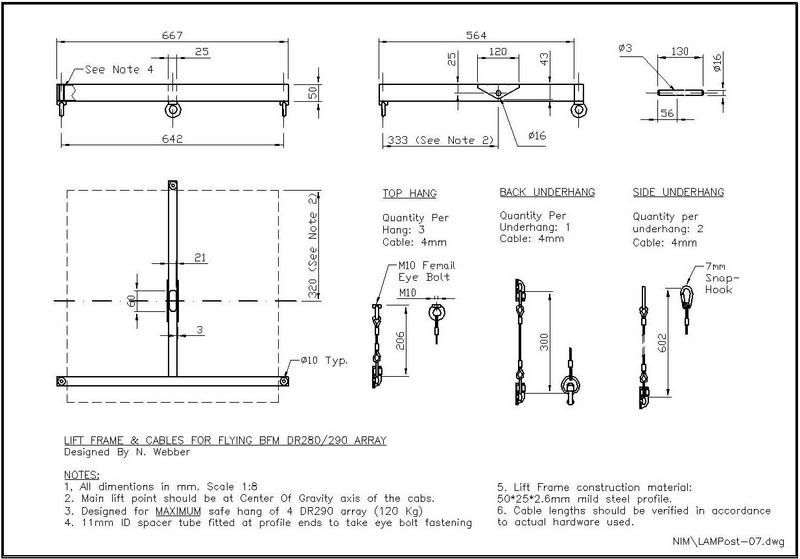
I have been asked by some readers regarding the flying hardware arrangement of my DR290s.
Ruther then answering each privately I am offering here the detailed design.
I've organized the drawings so that they are 'readable' to others beside my self…
I hope the drawings are clear to those who can understand them...
A few words though:
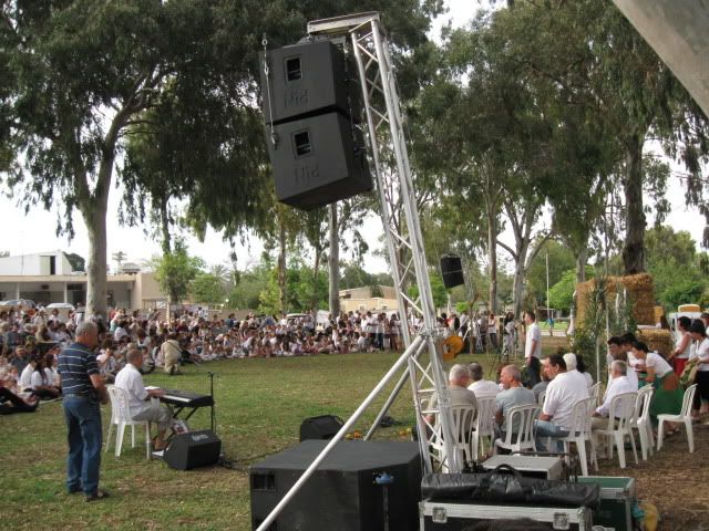
This flying system is actually part of my L.A.M.Post system
(learn more and see some pictures here: http://srforums.prosoundweb.com/index.p ... 198/0/0/0/
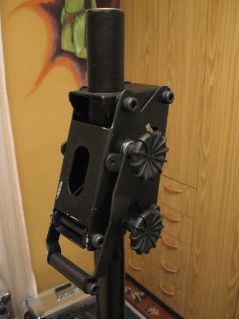
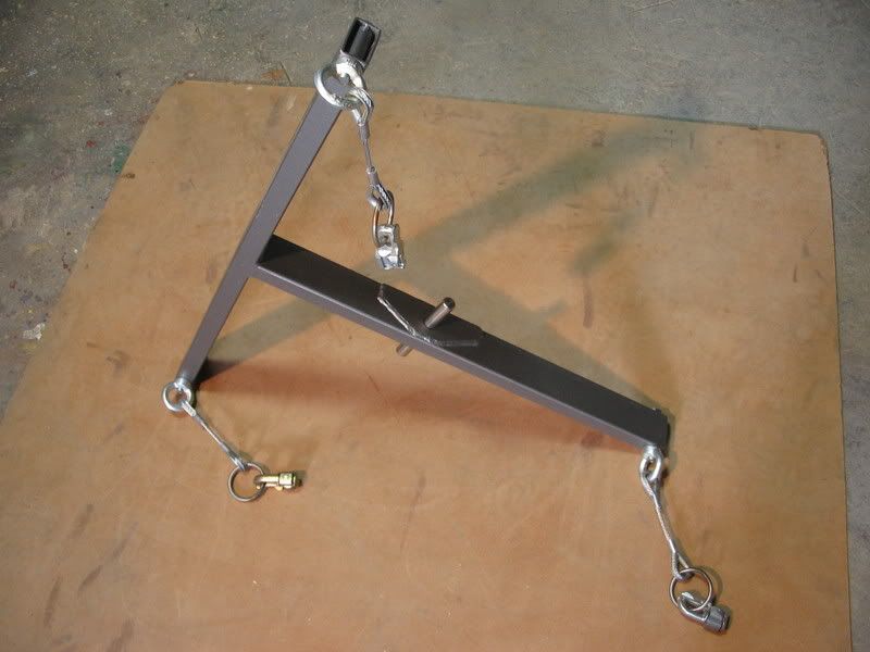
The main hang point/pin also functions as a safety anchor pin once engaged with the arrest hooks of the top beam.
This is also part of the mechanism for securing the array from rotating and swaying sideways.
Whatever system one uses to lift or hang the arrays by, these aspects must be addressed.
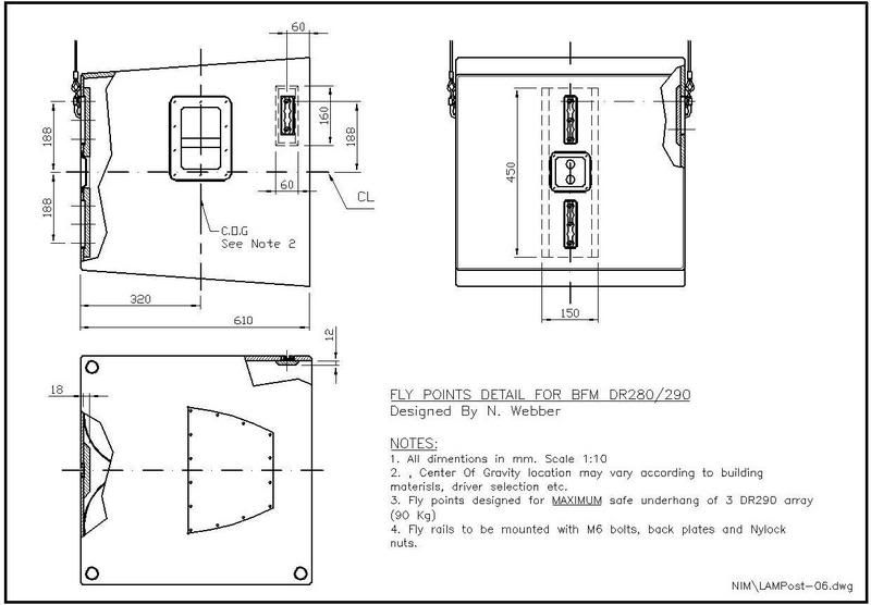
The placement of the main lift point (of the lift frame) was determined according to the COG point of my 290s.
Mine are loaded with the recommended drivers and horns, have front grills, and the hardware and reinforcement additions as shown.
Other/different builds and configurations may result in a different COG point and will require shifting this main lift point accordingly.
Here goes:
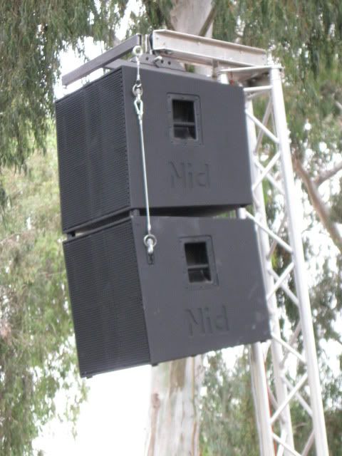
And this is how it all goes together:
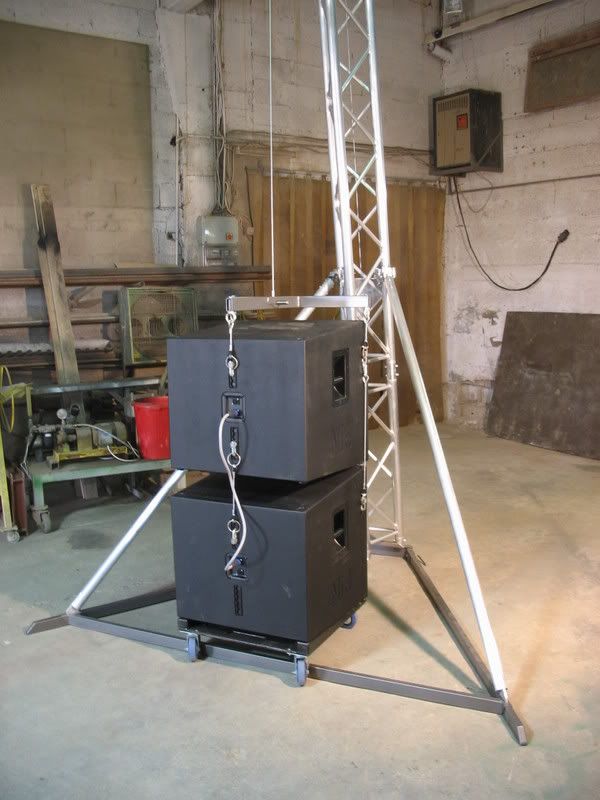
Edited: Added pictures...