I'd show it that way in the plans, but since not everyone happens to have strap clamps handy I didn't. Those who do have them know how to use them anyway. Besides, staples are faster, and Duratex hides all. As shown in the plans I use the guide board and clamp method at the joint with the sides, because there it gives a tighter joint than staples, unless you drive them every 1/2 inch.LelandCrooks wrote:Nice. Well done and thought out.
Second BFM Build: 2 x J12 Lites
-
Bill Fitzmaurice

- Site Admin
- Posts: 29153
- Joined: Tue May 02, 2006 5:59 pm
Re: Second BFM Build: 2 x J12 Lites
-
LelandCrooks

- Posts: 7242
- Joined: Thu May 04, 2006 9:36 am
- Location: Midwest/Kansas/Speaker Nirvana
- Contact:
Re: Second BFM Build: 2 x J12 Lites
Yea, you used to have the DR plans using strap clamps IIRC. I'm just partial to the fewer fasteners I can use the better. And that means clamps. Sanding and filling are the least fun part of the job.
If it's too loud, you're even older than me! Like me.
http://www.speakerhardware.com
http://www.speakerhardware.com
-
Charles Jenkinson

- Posts: 1127
- Joined: Sat Aug 06, 2011 3:25 pm
- Location: Manchester, UK
Re: Second BFM Build: 2 x J12 Lites
I tried sabblebacke for a price for piezos, but felt bad for not buying from him in the end, and bought from Leland - It was just too easy to get all crossover stuff as well. Oxon John, escape has bought piezos direct off monacor in the uk. I wish I'd have clamped both major and minor sheaths for gluing on. If one is a bit anal with filling and sanding, finishing over the staples is a PITA. The knack on clamping the minor sheaths is making sure they are properly touching the profiled ribs they stick down to, and are not held off due to the sheath jamming across the width, which has to be dressed accordingly at the sides.
Again, great progress Jools!
Again, great progress Jools!
2xJ12L (3012HO) switchable/melded
2xT30
Words&graphics - Audio&Acoustics - Hardware&DSP; 3 different paradigms.
2xT30
Words&graphics - Audio&Acoustics - Hardware&DSP; 3 different paradigms.

Re: Second BFM Build: 2 x J12 Lites
Monacor list their price as £5.47 each (over $100 per cab!), so it would cost more for 24 (the minimum for two J10Ls) than it would to get 50 from Leland including duties! So the decision for tweets and crossovers is pretty much made (although Blue Aran are good for hardware here in the UK), but I now have several sheath clamping methods to choose between. Anyway, I'm now in danger of hijacking Jools' thread so I'll shut up and wait for the next piccies.
John
John
Built: XF210
Building: None
Considering: Jack 10 Lites and Wedgehorn 6s
Building: None
Considering: Jack 10 Lites and Wedgehorn 6s
-
Hackomatic

- Posts: 400
- Joined: Thu Jun 25, 2009 8:11 am
- Location: West TN
Re: Second BFM Build: 2 x J12 Lites
Well CRAP! I hadn't considered building any J-lites, but this thread and Harley's have given me the fever. 
Jools . .nice build, nice pics, and even better running dialogue!
Jools . .nice build, nice pics, and even better running dialogue!
Dave H
Re: Second BFM Build: 2 x J12 Lites
Addicted!Hackomatic wrote:Well CRAP! I hadn't considered building any J-lites, but this thread and Harley's have given me the fever.
Jools . .nice build, nice pics, and even better running dialogue!
TomS
Re: Second BFM Build: 2 x J12 Lites
I don't believe that Peter Parker got bitten by a radioactive spider. I think that was just an elaborate ruse to cover the fact that he'd broken into Uncle Ben's workshop, stolen a couple of hot glue guns and stuffed them up his sleeves to make his getaway...all this superhero crime fighting stuff that came afterwards was just to show his remorse and make good his guilt over his criminal past.
How do I know? Well, I know that I haven't got "Spidey Powers" but I've been doing a pretty good impression with my own hot glue gun for a chunk of last week.
Slow progress last week. My wife went into hospital for a routine procedure (associated with her MS). It didn't go as smoothly as hoped and she had to spend a few days in there...nothing major, just observation, and she's fine now. However, the story from the doctors was "she should be out tomorrow", every day for four days and what with visiting, and never being quite sure when they'd phone to say she was ready to come home, I didn't want to be in the middle of clamping a PL soaked panel when the phone rang. I wanted to do something where I could easily put the job to one side and pick up where I'd left off; so I turned my attention to crossovers - hence the glue gun.
I've built BFM crossovers before, for my two W8 monitors, but I was under a bit of time pressure with upcoming gigs and I always felt that I'd rushed them. They're functional, and robust enough, but they sure ain't pretty. So, for the J12s I wanted to make a bit more of a decent job out of them.
Crossovers do make appearances in build threads, but most pics of them seem to arrive 'fully formed', so I thought I would post up a few pics of how I made mine. As always, I'm sure there are better ways, because I've seen other builds with far more professional, almost military spec crossovers; but...here goes.
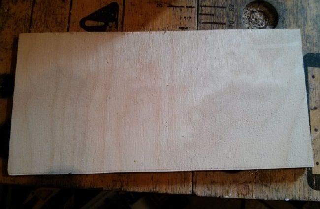
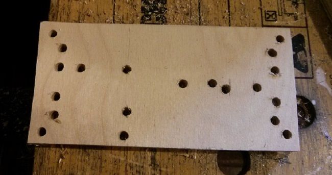
First simple step is to cut some 1/4" ply offcuts into as many 6" x 3" pieces as you need (two per cab)
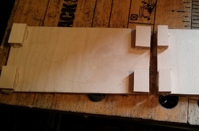
then, cut four little postage stamp sized pieces per 6 x 3

then hot glue these to each corner to make standoffs (seems obvious but I forgot them on the W8's and had to bodge some in after the soldering was done....better to do it first)
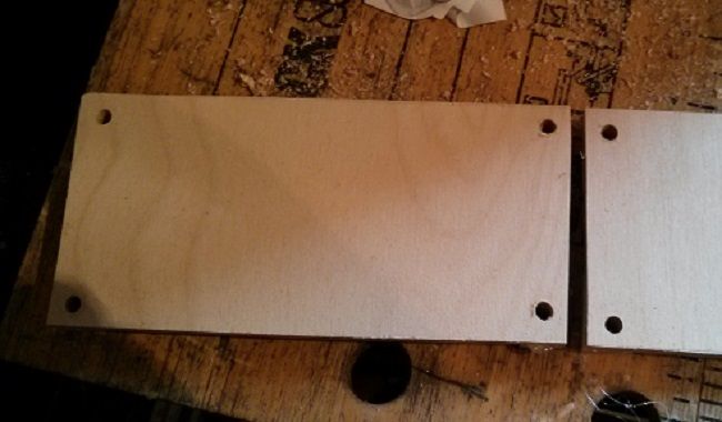
after that I drilled a 5mm hole in each standoff so I now have a blank crossover panel complete with mounting holes.
Next step was to take the various components, that I obtained from Leland months ago, loosely lay them into their approximate positions and scribble a little pencil mark to indicate where each of them sits.
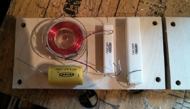
Then since you should still have the drill handy, put some 5mm holes either side of each component's location so that you can put a cable tie round each component as you build.
After that, the Spidey fun can begin, squeezing a bead of hot glue underneath each piece, press each component down onto it's bed of glue then tie it down tight with a cable tie...
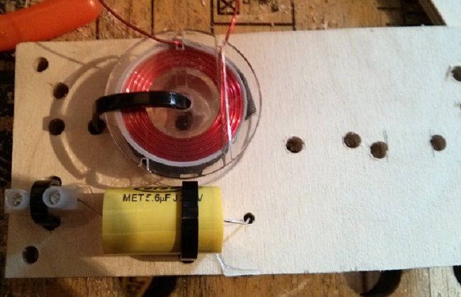
you can see in the above pic that I also drilled a smaller 3mm hole where each component lead needed to go. At this point I was called away and didn't take any more interim pics, but I kept on going with the component placement, gluing and cable ties until all the components were physically mounted. It was only after I had got all my components tied down that I got the soldering iron out and soldered each connection - you may prefer to solder as you go.
And I ended up with a finished high pass filter - don't worry folks...the 4 ohm resistor is wired in series, even though it's physically in parallel
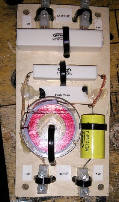
The final stage was to put a blob of hot glue over some of the pieces of wire that form parts of the +ve and -ve rails so that they don't come loose or rattle with vibration, and since I'm going back to other parts of the build now, such as doing the rest of the woodwork and making some melded arrays, it'll be a week or so until I come to mount the crossovers and my pea brain will have forgotten which way round the connections are without referring to the plans...so I got my Dymo labeller out and stuck a few labels about as reminders; should save a bit of time when installing them.
After that, you just rinse and repeat until you have them all done...the low pass filters only have two components, so they're a little bit easier, and the topography of my low pass layout is just a very literal translation of the circuit diagram onto the board...
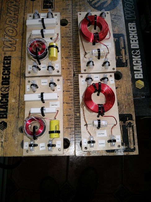
I know both high pass and low pass inductors are in the same orientation, but since I intend to mount the boards on either side of the cab there will be enough physical separation that they shouldn't interact.
OK...time to get on with my build now so "up, up and away".....Oh damn, got my Superheroes crossed over again...
How do I know? Well, I know that I haven't got "Spidey Powers" but I've been doing a pretty good impression with my own hot glue gun for a chunk of last week.
Slow progress last week. My wife went into hospital for a routine procedure (associated with her MS). It didn't go as smoothly as hoped and she had to spend a few days in there...nothing major, just observation, and she's fine now. However, the story from the doctors was "she should be out tomorrow", every day for four days and what with visiting, and never being quite sure when they'd phone to say she was ready to come home, I didn't want to be in the middle of clamping a PL soaked panel when the phone rang. I wanted to do something where I could easily put the job to one side and pick up where I'd left off; so I turned my attention to crossovers - hence the glue gun.
I've built BFM crossovers before, for my two W8 monitors, but I was under a bit of time pressure with upcoming gigs and I always felt that I'd rushed them. They're functional, and robust enough, but they sure ain't pretty. So, for the J12s I wanted to make a bit more of a decent job out of them.
Crossovers do make appearances in build threads, but most pics of them seem to arrive 'fully formed', so I thought I would post up a few pics of how I made mine. As always, I'm sure there are better ways, because I've seen other builds with far more professional, almost military spec crossovers; but...here goes.
First simple step is to cut some 1/4" ply offcuts into as many 6" x 3" pieces as you need (two per cab)
then, cut four little postage stamp sized pieces per 6 x 3
then hot glue these to each corner to make standoffs (seems obvious but I forgot them on the W8's and had to bodge some in after the soldering was done....better to do it first)
after that I drilled a 5mm hole in each standoff so I now have a blank crossover panel complete with mounting holes.
Next step was to take the various components, that I obtained from Leland months ago, loosely lay them into their approximate positions and scribble a little pencil mark to indicate where each of them sits.
Then since you should still have the drill handy, put some 5mm holes either side of each component's location so that you can put a cable tie round each component as you build.
After that, the Spidey fun can begin, squeezing a bead of hot glue underneath each piece, press each component down onto it's bed of glue then tie it down tight with a cable tie...
you can see in the above pic that I also drilled a smaller 3mm hole where each component lead needed to go. At this point I was called away and didn't take any more interim pics, but I kept on going with the component placement, gluing and cable ties until all the components were physically mounted. It was only after I had got all my components tied down that I got the soldering iron out and soldered each connection - you may prefer to solder as you go.
And I ended up with a finished high pass filter - don't worry folks...the 4 ohm resistor is wired in series, even though it's physically in parallel
The final stage was to put a blob of hot glue over some of the pieces of wire that form parts of the +ve and -ve rails so that they don't come loose or rattle with vibration, and since I'm going back to other parts of the build now, such as doing the rest of the woodwork and making some melded arrays, it'll be a week or so until I come to mount the crossovers and my pea brain will have forgotten which way round the connections are without referring to the plans...so I got my Dymo labeller out and stuck a few labels about as reminders; should save a bit of time when installing them.
After that, you just rinse and repeat until you have them all done...the low pass filters only have two components, so they're a little bit easier, and the topography of my low pass layout is just a very literal translation of the circuit diagram onto the board...
I know both high pass and low pass inductors are in the same orientation, but since I intend to mount the boards on either side of the cab there will be enough physical separation that they shouldn't interact.
OK...time to get on with my build now so "up, up and away".....Oh damn, got my Superheroes crossed over again...
2 x 3012 HO Jack 12 Lites
2 x Delta Pro 8b Wedgehorn 8 Monitors
Subs? Big question mark!
2 x Delta Pro 8b Wedgehorn 8 Monitors
Subs? Big question mark!

Re: Second BFM Build: 2 x J12 Lites
Go to monacor direct and ask for a quote for 50 (or how ever many you need). The price drop is quite dramatic for bulk orders (I think I ended up paying just under £3 each for 100). They think you are a business customer as you are ordering so many.... just play alongOxonjohn wrote:Monacor list their price as £5.47 each (over $100 per cab
-
Hackomatic
- Posts: 400
- Joined: Thu Jun 25, 2009 8:11 am
- Location: West TN
Re: Second BFM Build: 2 x J12 Lites
Not a thing wrong with those COs . . Plenty o' ties and Spidey spooge!
UNRELATED- Sure wish I had an old style B&D Workmate. They just don't build 'em like they used to . . .
UNRELATED- Sure wish I had an old style B&D Workmate. They just don't build 'em like they used to . . .
Dave H
-
Grant Bunter
- Posts: 6912
- Joined: Mon Nov 28, 2011 11:12 am
- Location: Ilfracombe Queensland Australia
- Contact:
Re: Second BFM Build: 2 x J12 Lites
Tidy work on the crossovers 
edit:
As long as they at least 6"/15cm apart, crosstalk with the inductors won't be a problem...
edit:
As long as they at least 6"/15cm apart, crosstalk with the inductors won't be a problem...
Built:
DR 250: x 2 melded array, 2x CD horn, March 2012 plans.
T39's: 4 x 20" KL3010LF , 2 x 28" 3012LF.
WH8: x 6 with melded array wired series/parallel.
Bunter's Audio and Lighting "like"s would be most appreciated...
DR 250: x 2 melded array, 2x CD horn, March 2012 plans.
T39's: 4 x 20" KL3010LF , 2 x 28" 3012LF.
WH8: x 6 with melded array wired series/parallel.
Bunter's Audio and Lighting "like"s would be most appreciated...
Re: Second BFM Build: 2 x J12 Lites
Kudos.Jools wrote: Crossovers do make appearances in build threads, but most pics of them seem to arrive 'fully formed', so I thought I would post up a few pics of how I made mine. As always, I'm sure there are better ways, because I've seen other builds with far more professional, almost military spec crossovers; but...here goes.
Nice easy build to follow.
TomS
Re: Second BFM Build: 2 x J12 Lites
Well, progress has slowed right down again. Every day last week seemed to have some sort of event that got in the way of any meaningful work on the J12Ls, so not a huge amount of progress to show...on the other hand I did decide to spend some time in an interim clean up: scraping excess PL, sanding, trimming off the excess from the major horn sheaths etc, and I'm sure I don't need to tell BFM veteran builders how much time that takes.
I did manage to install the minor sheaths on one cabinet, and before I did that I managed to catch and correct a minor ooops!!!
Right at the start of the build I had decided I wanted spring loaded handles, and so I backed up a patch in the side with another 6mm thickness so that, when the time came to fit the handles, I could route an 8mm recess and have enough thickness around the borders for screws - and make sure that everything remained airtight. I had placed these backers 3/4 of the way up the sides, but then I realised that once the sprung handles were in their carrying position, the handle itself would be more like 7/8 of the way up the cab. Now, I've carried enough different cabs over the years to have developed a real gripe about handles that are placed so that, when you're carrying the cab, the bottom of the cab is just around your mid-thigh or above your knees and stops you walking properly...I had cursed the designers of commercial cabs and thought "how hard can it be to put the handles in a better place, then realised with some dismay that I'd just created exactly that same scenario with my choice of position for my backing pieces.....curses!!!
Fortunately, I hadn't cut the holes for my top hats yet and because the J12L is conveniently symmetrical around both its horizontal and vertical axes there was no reason why it couldn't be flipped so that the top became the bottom...thereby putting the opened handles at mid cab height and neatly getting around the thigh slapping problem...So, I flipped my cab, cut the top hat hole and in doing so defined the bottom of the cab for all eternity.
Before I put in the duct braces I shamelessly copied Charles Jenkinson's solution to giving the top hat mounting screws something to bite into by tracing around the mounting flange, cutting a circle and then drilling a 45mm hole in the centre of it...making a sort of BB 'pineapple ring' to back up the base.
The duct braces, of course needed a little modification with a cut out to span the top hat backer.
I actually found the whole stage of installing the minor sheaths the most fiddly and time consuming part of the build so far. The top hat backer needed to be centred and glued up, then the duct braces needed to be shaped and glued up, then the duct itself needed some patient and careful shaping. The plans recommend doing the final shaping with a drum sander, which I don't have, so I started shaping them with a sanding block until I lost patience and did it with the jigsaw instead...building BFM cabs has sharpened up my jigsaw skills and I can now take off the merest sliver at each pass, so I did this on each side until they were a good fit. Once I had decided on this method each duct only took about 5 minutes to get into shape...but since I had taken the decision to let the PL cure sufficiently between each glue up so that a) nothing moved b) I didn't smear myself and everything around me with half cured PL, even getting to the point of gluing the ducts in took time (including working out the offset of where my brad gun actually fires and marking the duct out so that I would score a direct hit nailing it to the braces).
Talking about jigsaw skills...DONT do what I did to make the minor sheath braces. I had rough cut an individual rectangular blank to shape the brace from, but then you only have a small piece of wood to work with that is bloody difficult to hold, near impossible to clamp....so, I ended up holding the workpiece with my fingers far closer than I would like to the jigsaw blade. I made absolutely sure before I pulled the trigger that my fingers were safely out of any cutting trajectory, and concentrated like hell while the jigsaw was whirring...nonetheless, you'll be doing yourself a favour if you cut the braces out of a piece of wood that is big enough to retain a sensible clamping surface (or at least gets your fingers well out of the way)...anyway, no harm done, but I will be following my own advice on the next cab. In the picture above it's just dry fitted to check it's positioning, and you can also see the 1/8" offcut that I used to check the clearance with the baffle cut out.
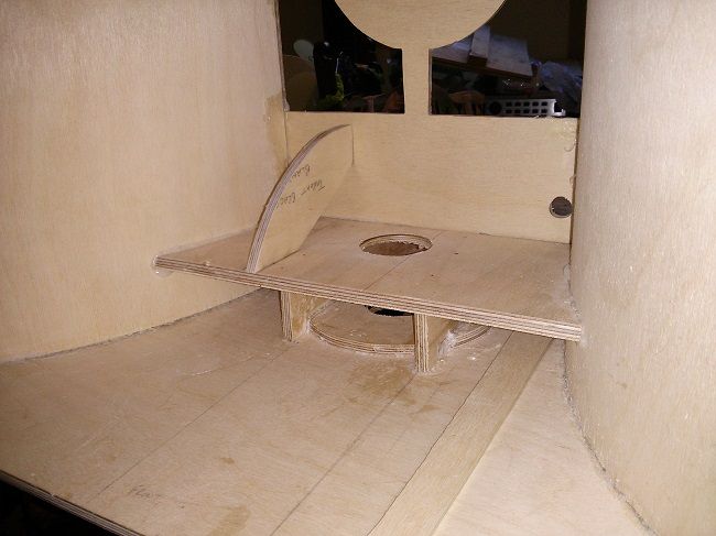
And after what seemed like a lot of fiddling I finally got both braces hot glued in place...

I then installed the top hat and PL'd around it to make what I hope will prove to be an airtight seal...I used the plastic bag method to do this, firstly squirting a good old bead of PL all around the top hat, then tearing a piece off a polythene bag, wrapping it around my finger and working the PL into the gap.
When the PL had cured it was onto bending the minor sheath. I used my strap clamp method to do this, as I had done with the major horn sheaths...but it is more difficult to do. The radius is tighter and the sheath is not as big so you have less leverage to make a tighter curve. Shaping the minor sheath so that it fits the radius of the major sheath at the edges takes patience, and it pays to leave a bit of clearance because if it binds even slightly it will stop the curve being formed...but when it's done...I'll confess to being a bit nerdy here, there is something deeply satisfying about the compound curve where these two curved surfaces meet...like the curves you find on performance cars and superbikes.
So here's the progress on one of the cabs so far...
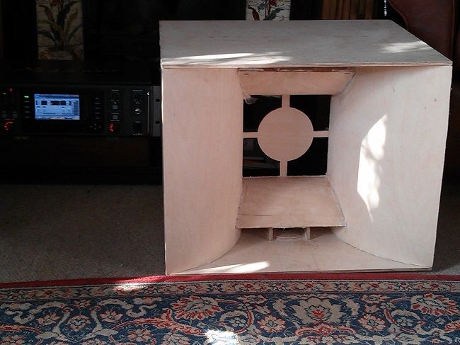
The upper duct looks a bit skewed, but this is due to the fact that the sheath hasn't been trimmed yet and sticks up further on the left... there is also some PL squeeze out, when this is trimmed up it will be fine.
You can also see my new X32 Rack lurking in the background and I'm having great fun learning my way around this...
I'm hoping to put a big push in on the J12s in the coming week, first getting the second cab to this stage, then finishing up all the woodwork on both cabs and onto a bit of melded array building by next weekend...but we'll see.
I did manage to install the minor sheaths on one cabinet, and before I did that I managed to catch and correct a minor ooops!!!
Right at the start of the build I had decided I wanted spring loaded handles, and so I backed up a patch in the side with another 6mm thickness so that, when the time came to fit the handles, I could route an 8mm recess and have enough thickness around the borders for screws - and make sure that everything remained airtight. I had placed these backers 3/4 of the way up the sides, but then I realised that once the sprung handles were in their carrying position, the handle itself would be more like 7/8 of the way up the cab. Now, I've carried enough different cabs over the years to have developed a real gripe about handles that are placed so that, when you're carrying the cab, the bottom of the cab is just around your mid-thigh or above your knees and stops you walking properly...I had cursed the designers of commercial cabs and thought "how hard can it be to put the handles in a better place, then realised with some dismay that I'd just created exactly that same scenario with my choice of position for my backing pieces.....curses!!!
Fortunately, I hadn't cut the holes for my top hats yet and because the J12L is conveniently symmetrical around both its horizontal and vertical axes there was no reason why it couldn't be flipped so that the top became the bottom...thereby putting the opened handles at mid cab height and neatly getting around the thigh slapping problem...So, I flipped my cab, cut the top hat hole and in doing so defined the bottom of the cab for all eternity.
Before I put in the duct braces I shamelessly copied Charles Jenkinson's solution to giving the top hat mounting screws something to bite into by tracing around the mounting flange, cutting a circle and then drilling a 45mm hole in the centre of it...making a sort of BB 'pineapple ring' to back up the base.
The duct braces, of course needed a little modification with a cut out to span the top hat backer.
I actually found the whole stage of installing the minor sheaths the most fiddly and time consuming part of the build so far. The top hat backer needed to be centred and glued up, then the duct braces needed to be shaped and glued up, then the duct itself needed some patient and careful shaping. The plans recommend doing the final shaping with a drum sander, which I don't have, so I started shaping them with a sanding block until I lost patience and did it with the jigsaw instead...building BFM cabs has sharpened up my jigsaw skills and I can now take off the merest sliver at each pass, so I did this on each side until they were a good fit. Once I had decided on this method each duct only took about 5 minutes to get into shape...but since I had taken the decision to let the PL cure sufficiently between each glue up so that a) nothing moved b) I didn't smear myself and everything around me with half cured PL, even getting to the point of gluing the ducts in took time (including working out the offset of where my brad gun actually fires and marking the duct out so that I would score a direct hit nailing it to the braces).
Talking about jigsaw skills...DONT do what I did to make the minor sheath braces. I had rough cut an individual rectangular blank to shape the brace from, but then you only have a small piece of wood to work with that is bloody difficult to hold, near impossible to clamp....so, I ended up holding the workpiece with my fingers far closer than I would like to the jigsaw blade. I made absolutely sure before I pulled the trigger that my fingers were safely out of any cutting trajectory, and concentrated like hell while the jigsaw was whirring...nonetheless, you'll be doing yourself a favour if you cut the braces out of a piece of wood that is big enough to retain a sensible clamping surface (or at least gets your fingers well out of the way)...anyway, no harm done, but I will be following my own advice on the next cab. In the picture above it's just dry fitted to check it's positioning, and you can also see the 1/8" offcut that I used to check the clearance with the baffle cut out.
And after what seemed like a lot of fiddling I finally got both braces hot glued in place...
I then installed the top hat and PL'd around it to make what I hope will prove to be an airtight seal...I used the plastic bag method to do this, firstly squirting a good old bead of PL all around the top hat, then tearing a piece off a polythene bag, wrapping it around my finger and working the PL into the gap.
When the PL had cured it was onto bending the minor sheath. I used my strap clamp method to do this, as I had done with the major horn sheaths...but it is more difficult to do. The radius is tighter and the sheath is not as big so you have less leverage to make a tighter curve. Shaping the minor sheath so that it fits the radius of the major sheath at the edges takes patience, and it pays to leave a bit of clearance because if it binds even slightly it will stop the curve being formed...but when it's done...I'll confess to being a bit nerdy here, there is something deeply satisfying about the compound curve where these two curved surfaces meet...like the curves you find on performance cars and superbikes.
So here's the progress on one of the cabs so far...
The upper duct looks a bit skewed, but this is due to the fact that the sheath hasn't been trimmed yet and sticks up further on the left... there is also some PL squeeze out, when this is trimmed up it will be fine.
You can also see my new X32 Rack lurking in the background and I'm having great fun learning my way around this...
I'm hoping to put a big push in on the J12s in the coming week, first getting the second cab to this stage, then finishing up all the woodwork on both cabs and onto a bit of melded array building by next weekend...but we'll see.
2 x 3012 HO Jack 12 Lites
2 x Delta Pro 8b Wedgehorn 8 Monitors
Subs? Big question mark!
2 x Delta Pro 8b Wedgehorn 8 Monitors
Subs? Big question mark!
Re: Second BFM Build: 2 x J12 Lites
Well, I've managed to get a few hours building in across the last few afternoons. Unfortunately, I forgot to tell my brain that I was doing it, so I've had my first real crop of stupid mistakes so far on this build.
On Tuesday, I bought the second cab up to the same level as the cab in the post above, getting the ducts and the throat sheaths installed. Again, I found this phase of fitting backers for the top hat...letting the PL dry, fitting the duct braces...letting the PL dry etc...more time consuming and fiddly than I expected it to be. As well as this I realised, when the bottom duct had been shaped, glued and pinned into position with brads for 15 minutes (and the PL bond was already unbreakable) that I had forgotten to put the 30 degree bevel on the leading edge
I had to wait until the PL had cured then get a rasp and sanding sticks on the leading edge to put the bevel on in-situ, which was a real bitch of a job...."Ah well" I thought as I rasped away "At least I'm wised up for the next one", then promptly did exactly the same thing with the top duct
Persistence eventually prevailed and I got the throat sheaths in place on the second cabs, although I still have a couple of hairline gaps where I can't be certain that the PL is fully airtight, it may have expanded on the inside to make a seal but...anyway, one of the jobs to do before I go much further is to go over all the cab seams with a bead of sealant so that'll get done.
Didn't take any pics 'cos I did all that with the first cab.
Brainless day number two came when I had an hour or so to spare yesterday, all I wanted to do was make the driver spacers...easy peasy right? Just laminate two 6mm pieces together to make a 12mm spacer, well...
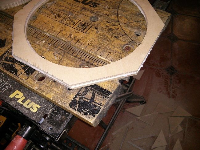
It started out OK with a nice clean bit of jigsaw work...
Now to laminate them...
My rationale was that I only have about 1/3 of a tube of PL left until I take a trip into town to get some more. I thought that I would have enough PL for the remaining glue up tasks needed to complete both cabs...but not if I have to glue up a couple of square spacer blanks. So I decided to cut out two spacers and laminate them together once they were shaped, that way I wouldn't use up so much PL...so that's what I did.
But, Jools...you know PL slithers and slides all over the place...and so it proved! I tried in vain to get it all lined up nicely. When the driver hole was lined up the hexagonal bits weren't and vice versa and, although I'm getting quite good at avoiding covering myself and everything else in sight with PL, this was not one of those times. You can never have enough clamps and look...I didn't...
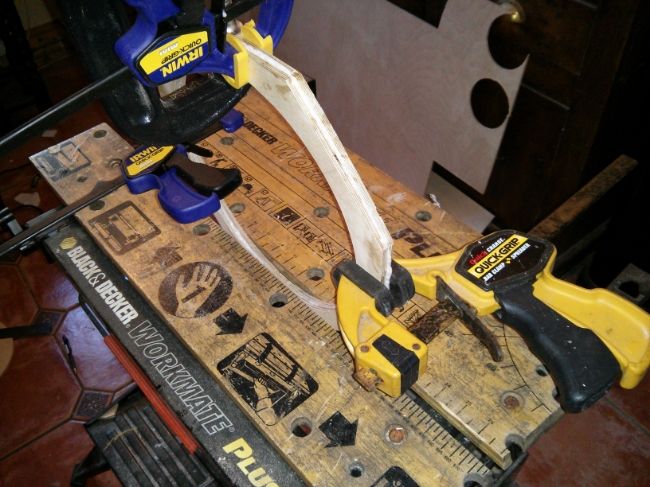
So after wrestling with staples, clamps and removing PL from everything it had smeared onto I ended up with a rubbish attempt at a woofer spacer that was completely out of whack and only fit for the trash.
Ooops...time for a rethink!
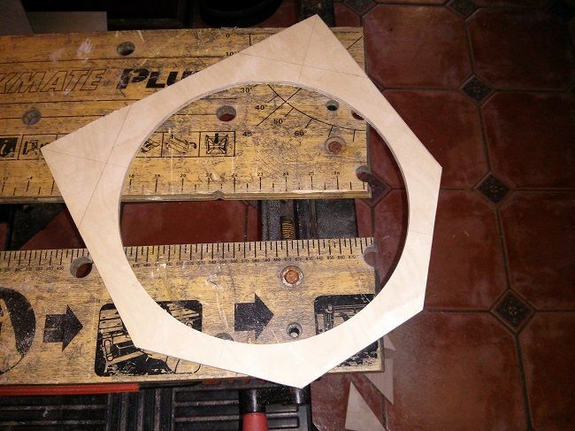
So next, I drew out the spacer on two rectangular blanks....put PL just on the drawn out spacer shape and clamped the two rectangles together
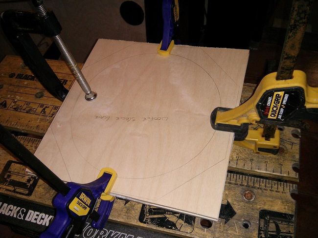
Let the PL cure for 30 minutes and then another 10 minutes with the jigsaw and I finally had one decent woofer spacer...
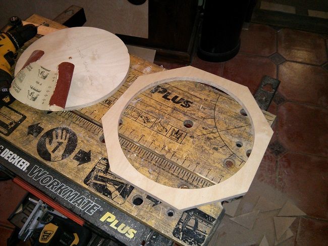
Not bad for TWO AND A HALF HOURS WORK!!!!
And it was only after all that that I re-read the plans for the umpteenth time and thought..."why didn't you just staple the lams together like it says in here"....ARRRRRRRRGGGGHHHH
On Tuesday, I bought the second cab up to the same level as the cab in the post above, getting the ducts and the throat sheaths installed. Again, I found this phase of fitting backers for the top hat...letting the PL dry, fitting the duct braces...letting the PL dry etc...more time consuming and fiddly than I expected it to be. As well as this I realised, when the bottom duct had been shaped, glued and pinned into position with brads for 15 minutes (and the PL bond was already unbreakable) that I had forgotten to put the 30 degree bevel on the leading edge
I had to wait until the PL had cured then get a rasp and sanding sticks on the leading edge to put the bevel on in-situ, which was a real bitch of a job...."Ah well" I thought as I rasped away "At least I'm wised up for the next one", then promptly did exactly the same thing with the top duct
Persistence eventually prevailed and I got the throat sheaths in place on the second cabs, although I still have a couple of hairline gaps where I can't be certain that the PL is fully airtight, it may have expanded on the inside to make a seal but...anyway, one of the jobs to do before I go much further is to go over all the cab seams with a bead of sealant so that'll get done.
Didn't take any pics 'cos I did all that with the first cab.
Brainless day number two came when I had an hour or so to spare yesterday, all I wanted to do was make the driver spacers...easy peasy right? Just laminate two 6mm pieces together to make a 12mm spacer, well...
It started out OK with a nice clean bit of jigsaw work...
Now to laminate them...
My rationale was that I only have about 1/3 of a tube of PL left until I take a trip into town to get some more. I thought that I would have enough PL for the remaining glue up tasks needed to complete both cabs...but not if I have to glue up a couple of square spacer blanks. So I decided to cut out two spacers and laminate them together once they were shaped, that way I wouldn't use up so much PL...so that's what I did.
But, Jools...you know PL slithers and slides all over the place...and so it proved! I tried in vain to get it all lined up nicely. When the driver hole was lined up the hexagonal bits weren't and vice versa and, although I'm getting quite good at avoiding covering myself and everything else in sight with PL, this was not one of those times. You can never have enough clamps and look...I didn't...
So after wrestling with staples, clamps and removing PL from everything it had smeared onto I ended up with a rubbish attempt at a woofer spacer that was completely out of whack and only fit for the trash.
Ooops...time for a rethink!
So next, I drew out the spacer on two rectangular blanks....put PL just on the drawn out spacer shape and clamped the two rectangles together
Let the PL cure for 30 minutes and then another 10 minutes with the jigsaw and I finally had one decent woofer spacer...
Not bad for TWO AND A HALF HOURS WORK!!!!
And it was only after all that that I re-read the plans for the umpteenth time and thought..."why didn't you just staple the lams together like it says in here"....ARRRRRRRRGGGGHHHH
2 x 3012 HO Jack 12 Lites
2 x Delta Pro 8b Wedgehorn 8 Monitors
Subs? Big question mark!
2 x Delta Pro 8b Wedgehorn 8 Monitors
Subs? Big question mark!
Re: Second BFM Build: 2 x J12 Lites
That was all yesterday....
It's Valentines Day today, so I didn't want to subject Mrs Jools to sawdust and glue in the kitchen, but my brainless trait continued when she asked me what my plans for the day were...
"Oh, I'm just going to excite a couple of HOs with a few hours of vibration treatment" probably wasn't the best way to put it...but it's true.
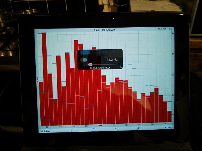
Here are the pair of 3012HOs in question...
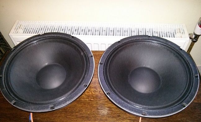
being excited by a signal generator function on an iPad RTA app.
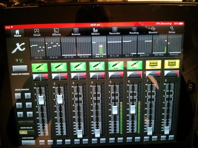
Then through the X32 iPad App - with the faders on a couple of Aux inputs set to obtain 10 volts from the poweramp
Which is wirelessly controlling my new X32 rack....
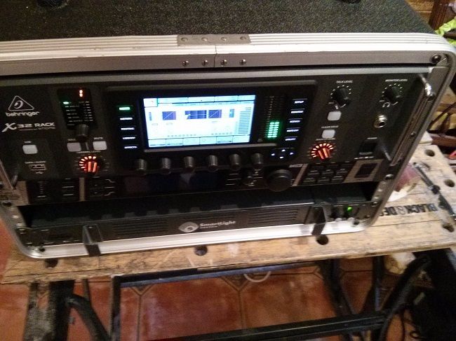
I've only had it a couple of weeks and haven't used it with the band yet, because work commitments mean that we're not rehearsing again until Feb 25th, but I already love this thing. I've set it up with a baseline config for the band and reduced the whole PA to this rack...which currently has just the X32, a DEQ2496 and a 1U 300 watt per side power amp in it. I'm waiting to see if I can afford one of those Synq 1K0 amps to fill the spare 1U space...in that case the synq will power the J12s and the current amp will be put to powering a couple of monitor channels...since each bus output on the X32 has a 6 band parametric and it's also possible to insert a 31 band graphic on each mix bus ahead of the parametric, it may be possible to lose the DEQ as well...especially since the V2.0 firmware has got SMAART like RTA functions built in
It's Valentines Day today, so I didn't want to subject Mrs Jools to sawdust and glue in the kitchen, but my brainless trait continued when she asked me what my plans for the day were...
"Oh, I'm just going to excite a couple of HOs with a few hours of vibration treatment" probably wasn't the best way to put it...but it's true.
Here are the pair of 3012HOs in question...
being excited by a signal generator function on an iPad RTA app.
Then through the X32 iPad App - with the faders on a couple of Aux inputs set to obtain 10 volts from the poweramp
Which is wirelessly controlling my new X32 rack....
I've only had it a couple of weeks and haven't used it with the band yet, because work commitments mean that we're not rehearsing again until Feb 25th, but I already love this thing. I've set it up with a baseline config for the band and reduced the whole PA to this rack...which currently has just the X32, a DEQ2496 and a 1U 300 watt per side power amp in it. I'm waiting to see if I can afford one of those Synq 1K0 amps to fill the spare 1U space...in that case the synq will power the J12s and the current amp will be put to powering a couple of monitor channels...since each bus output on the X32 has a 6 band parametric and it's also possible to insert a 31 band graphic on each mix bus ahead of the parametric, it may be possible to lose the DEQ as well...especially since the V2.0 firmware has got SMAART like RTA functions built in
2 x 3012 HO Jack 12 Lites
2 x Delta Pro 8b Wedgehorn 8 Monitors
Subs? Big question mark!
2 x Delta Pro 8b Wedgehorn 8 Monitors
Subs? Big question mark!
Re: Second BFM Build: 2 x J12 Lites
In one of Harley's J12 Lite threads he said something to the effect of "this seemed like a mission that was never ending"....
I've had these words on my mind a lot in the last couple of weeks because I set myself a target of having these built by our next gig, this coming Saturday on March 1st. There is a LOT of work in these bad boys, it's taken me about a week of solid graft to take one of the cabs from "the white" (where the cabs have their throat and horn sheaths installed and all the bracing in) to the finished article...well, finished and functional albeit with a short snagging list.
There have also been plenty of times where the air has been thick with prime Anglo Saxon swear words and I have been ready to throw the towel in. Some of the "little jobs" have taken hours more than expected, but I did manage to get one finished yesterday in time for our pre-gig rehersal last night.
Results, even with a very quick and dirty RTA, were encouraging...which is just as well...because I've now got to try and take the second cab through to completion in half the time it took me to do the first from where it's at now. Time to dig deep and crack on.
I did take pics, but no time to post....
2 x 3012 HO Jack 12 Lites
2 x Delta Pro 8b Wedgehorn 8 Monitors
Subs? Big question mark!
2 x Delta Pro 8b Wedgehorn 8 Monitors
Subs? Big question mark!