OTop12 Build Thread

Post your build odyssey here.
Message
Author
miked
Posts: 1209
Joined: Fri Oct 23, 2009 4:18 am
Location: San Antonio, TX

Re: OTop12 Build Thread

#31 Post by miked »

Thanks, pal! To cut the 26-degree compound angles, I "crept on the cut" as you suggested and it worked like a charm. Didn't quite understand exactly how to do that until tonight.

Mark the workpiece first (a PITA when there's 8 of them), set the miter gauge to the proper angle, place the workpiece on the miter gauge to where it "looks right" and gently slide it into the blade, making a small cut. "Too much to the left." Tap the workpiece to the left "that much." Lather, rinse, repeat until it's right. I learned a whole lot tonight!

The reflectors took me a week to figure out and cut. Next time I have to make this same cut, it'll take just a few minutes to sort out how to do it. It was a good day. :hyper:

Just a little more cutting to do before assembly. I still need to get the crossovers and Duratex from Leland. That's next week.

Grant Bunter
Posts: 6912
Joined: Mon Nov 28, 2011 11:12 am
Location: Ilfracombe Queensland Australia
Contact:

Re: OTop12 Build Thread

#32 Post by Grant Bunter »

I knew you would get there!

There'll be some other challenges along the way, but it's all good learning :)
Built:
DR 250: x 2 melded array, 2x CD horn, March 2012 plans.
T39's: 4 x 20" KL3010LF , 2 x 28" 3012LF.
WH8: x 6 with melded array wired series/parallel.
Bunter's Audio and Lighting "like"s would be most appreciated...

miked
Posts: 1209
Joined: Fri Oct 23, 2009 4:18 am
Location: San Antonio, TX

Re: OTop12 Build Thread

#33 Post by miked »

Grant Bunter wrote:I knew you would get there!

There'll be some other challenges along the way, but it's all good learning :)
Whaaaat? There's MORE challenges to OTops? Crap, I quit! j/k

Those compound cuts sucked, man. But I tell you, I've learned a whole lot in a few days. I'm ready for the challenges! I'm also ready to have to do a bit of hand-sanding in order to fit all the parts together during assembly. I didn't "rough cut" anything. All the pieces are cut to as-assembled size, angles included. But, being human, I'm sure something is off, somehow. I'm hoping that my attention to detail in the cutting phase will translate to "ease of assembly" in the assembly phase. But I'm ready to adapt and overcome!

Bruce Weldy
Posts: 8539
Joined: Fri Nov 27, 2009 11:37 am
Location: New Braunfels, TX

Re: OTop12 Build Thread

#34 Post by Bruce Weldy »

miked wrote: All the pieces are cut to as-assembled size, angles included.
I did the same on all of my builds and never had a glitch. Went together like tinkertoys......(that will have some of the young-un's reachin' for google)

You really shouldn't have any hand-sanding to do. Any minor aberrations will be filled with the PL.

6 - T39 3012LF
4 - OT12 2512
1 - T24
1 - SLA Pro
2 - XF210


"A system with a few knobs set up by someone who knows what they are doing is always better than one with a lot of knobs set up by someone who doesn't."

miked
Posts: 1209
Joined: Fri Oct 23, 2009 4:18 am
Location: San Antonio, TX

Re: OTop12 Build Thread

#35 Post by miked »

:? I certainly hope you're right, Bruce. I'm not planning on cutting any pieces over...especially those horn reflectors.

Didn't get too much done today; I got distracted by other things...just one of those days. Keep in mind I'm building 4 OTops at the same time. Lots of pieces to deal with. At least there's progress; got the handle holes cut out. Still need to round them over though.

Marked the centers for the 1.5" holes. BTW: Per the plans, you can pretty much put the handle holes wherever you want. The plans show them centered on the side panels...and Bill has a reason for every single thing he does with these cabs. So mine are centered on the side panels. The centers of the holes are 2.5" down from the top edge. YMMV. 2.5" looked good to me.
Image

All holes cut. Took forever b/c of my baby drill press. The motor bogs down to a halt with anything larger than a 1/2" bit.
Image

Offending drill press. I sense a new machine in my near future.
Image

Finally got to use the edge guide for my router. It's "reach" is so small that I never get to use it for anything. It sure came in handy tonight. This was much easier than having to use the jigsaw...can't stand that little buzz bomb. The really nice thing about this particular edge guide is the micro-adjustment knob on the extreme right. After you set the rough width of the cut using the two wing nuts on the router base, that micro-adjust knob lets you slide the router bit about a 1/2" left/right in very small steps. It's perfect for this exact type of cut. I.E. perfect for "creeping up" on cut lines. Of course, that assumes you lined up the two big holes that you are trying to connect, perfectly in the first place. :?
Image

Nice handle hole. Still need to roundover though. Tomorrow.
Image

User avatar
Tom Smit
Posts: 7569
Joined: Sat Jan 05, 2008 1:24 pm
Location: Sarnia, Ont. Canada

Re: OTop12 Build Thread

#36 Post by Tom Smit »

Your making progress! Great! :clap:
TomS

miked
Posts: 1209
Joined: Fri Oct 23, 2009 4:18 am
Location: San Antonio, TX

Moving forward...

#37 Post by miked »

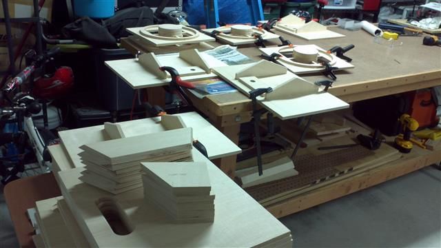
Slowly but surely, I'm getting there. At this point the only things left to cut are the spacer rings, the back braces and the strips that frame the rear opening. The rings will be a couple hours worth of work for me. The other parts I can knock out in a few minutes. You don't realize just how many parts are in one of these cabs until you build one! Of course, the fact I'm building 4 at the same time compounds things a bit. It will REALLY be interesting building 4 Titans at the same time, but that's at least two months off.

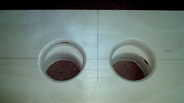
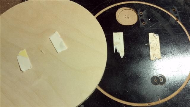
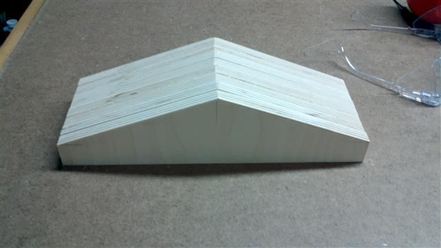
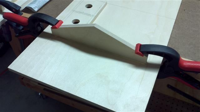
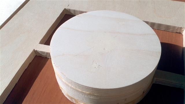
To build my phase plug extensions I drove a few sheetrock screws through the whole stack to clamp it while glue dried. This left big holes in the stack and some ply tearout when I removed the screws. It's probably not necessary, but I patched the holes with wood putty. The repair isn't 100% perfect, but it's 99% better than it was.

Patched/sanded plug.
Image

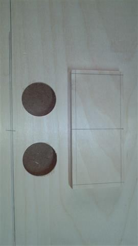
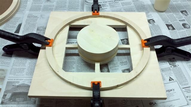
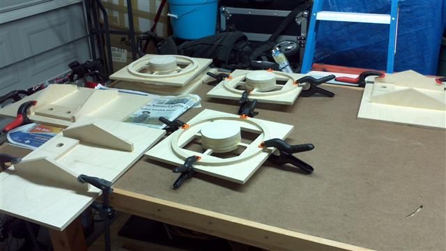
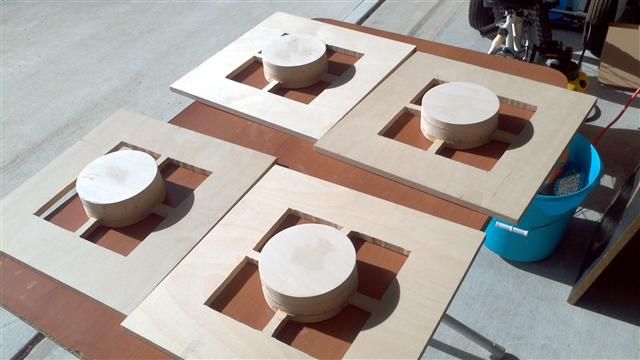
All four baffles/plugs. This is as nice as I'm making them as I've already spent almost as much time on just the baffles as I have on all the other parts.
Image

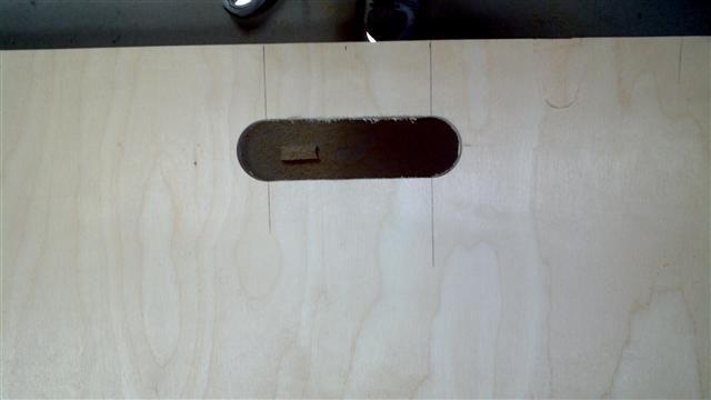
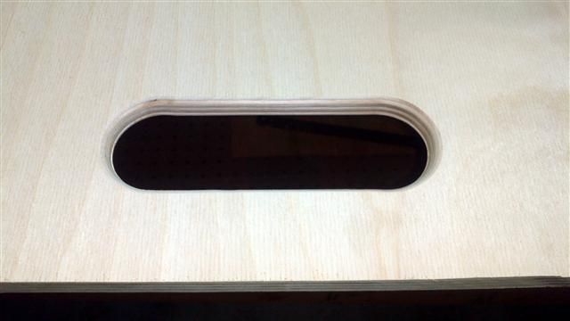
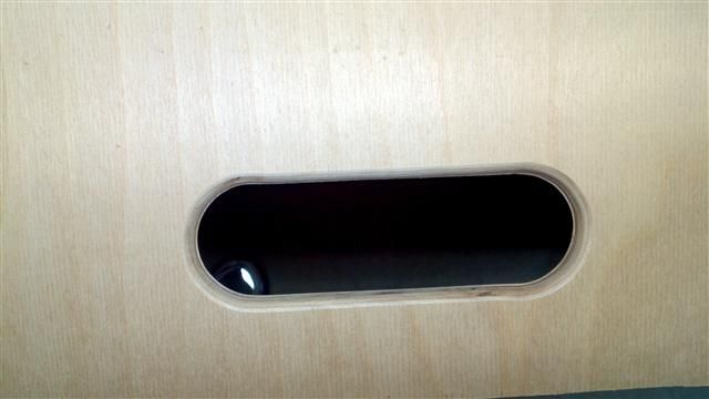
I used a 1/2" roundover and cleaned up the handle holes in the sides. They aren't all identical, but 5 out of the 8 sides look pretty much like this. I won't show you the other 3. :? They aren't bad, but they aren't perfect ovals. I chose my pics carefully. :D For anyone that hasn't built Omni's before, these pics are after I cleaned up the handle holes w/120-grit sandpaper. The 1/2" roundover on both sides left a very thin raised line at the center of the hole. I just wanted to be totally clear on expectation management.
Image
Image

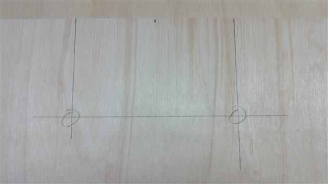
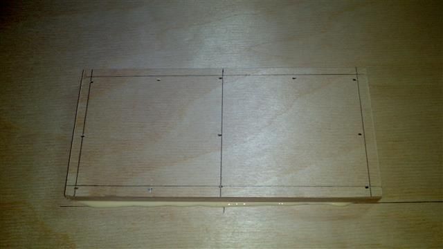
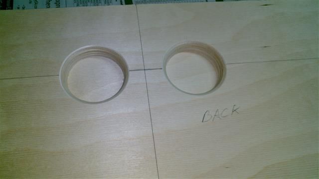
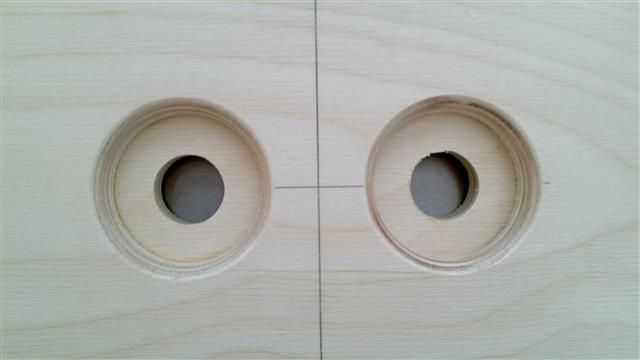
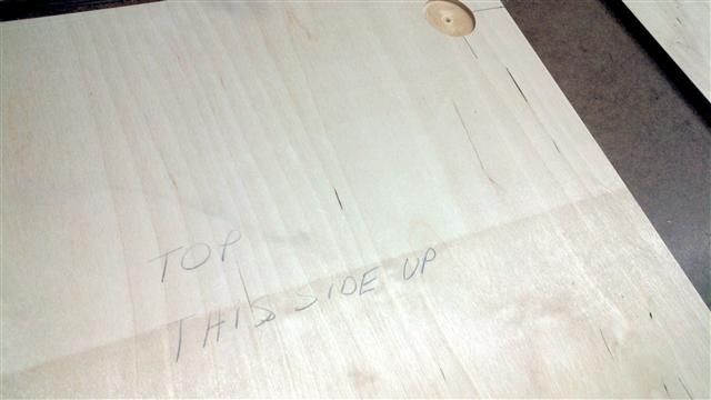
I marked the locations for the feet and clearly marked the bottoms/tops. The bottoms have the "x" marks where the feet are centered on. I'll predrill a pilot hole and stick a toothpick in there before Duratexing so I don't lose the location I so carefully marked. Ask me WHY I know to do that. :bash:

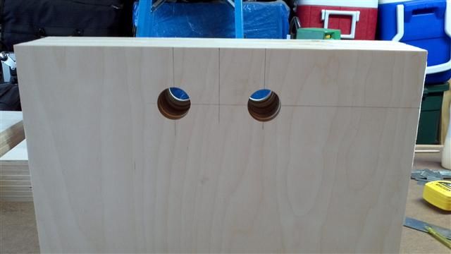
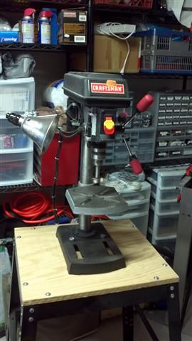
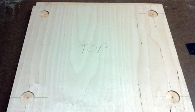
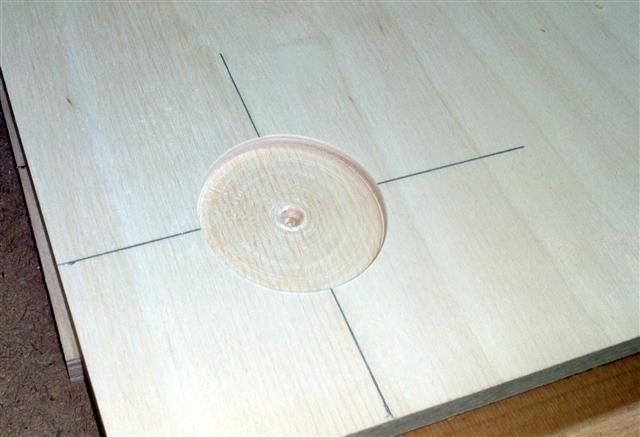
Here's a pic of one of the tops. I made recesses for the feet b/c I want the cabs to stack securely. Much easier/neater to cut these holes now before Duratexing. The recesses are about 1/8" deep. I eyeballed it on a piece of scrap before setting the depth stop on the drill press. It is what it is. The feet I'm using are the ubiquitous PennElecom F1686. These holes are 1 5/8" in diameter which leaves roughly 1/8" all around the foot...a little wiggle room, if you will.
Image
Image
Image

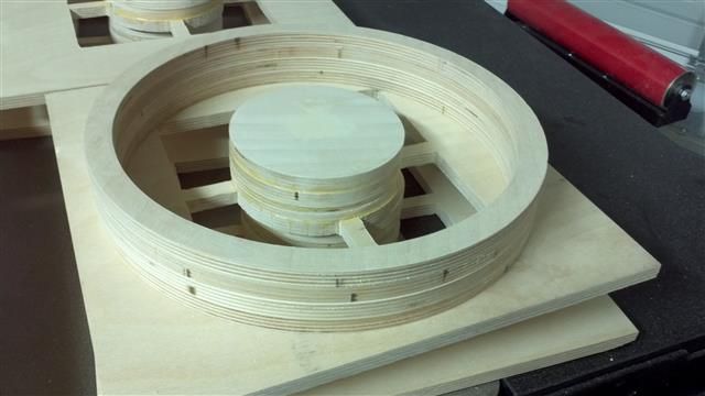
I did some dry test fitting and it looks like everything will go together smoothly except for the throat reflectors. I might have to sand them a bit, but it's sort of hard to tell when you're holding 8 different pieces together with two hands and a knee while trying to fit a 9th piece in there...just impossible to hold everything at 90 and 45 and 26 whatever degrees.

In other news, it looks like my idea to have the tophat mounted at the cab's COG will JUST work. If I orient the driver on the baffle so that an opening in the frame lines up with where the tophat comes through, the tophat should protrude into the "cone area" on the back of the driver around 1/8" or so. Nowhwere near the back of the cone, but worth mentioining.

Just to help you visualize what I'm talking about, look at this pic (not my pic: credit to Loudsubz). See where the four nuts are on the bottom of the cab? He has an external tophat mounted there. Imagine the driver rotated so that one of those square openings in the basket directly faces the floor of the cab. The tophat comes through right there, protruding just a hair into the "cone area." If I was using one of the Neo drivers with it's wee little magnet, this would be a non-issue. But, I happen to be using the same monstrous Delta Pro as pictured here.

Image


I'm excited about this. AFAIK, no one has done this before. It would be nice to "invent a feature" for these cabs that nobody has done before. Needless to say, not having to deal with any funky balancing act issues, tilting the speaker stands with shims, etc would be optimal.

More tomorrow. Assembly this weekend for sure.

ps
As I'm sure you've noticed, I've not mentioned anything about the piezo arrays. Haven't done a darn thing with them yet. :noob: I want the cabs done, to include Duratex before I even mess with them. Not looking forward to that part at all.

miked
Posts: 1209
Joined: Fri Oct 23, 2009 4:18 am
Location: San Antonio, TX

Incremental update

#38 Post by miked »

Didn't have much time to work on them tonight, but at least I figured out my jack/jackplate situation. I figured why spend $5 apiece on jack plates when the standard "countersunk hole" would work just fine?

So, I marked a line at the center of one long side of the back. I measured down 3" from the edge, then 1 3/4" to either side of the center line. I drilled 1 5/8" holes and rounded them over with a 1/2" roundover bit. Here's what that looks like.

Image

Then, taking into account the 1" filler/rear panel mounting strip, and leaving a little wiggle room, I marked 1 3/8" from the long edge and drew a line...er...twice in this pic. The proper 1 3/8" mark is the line to the right. You can see the backer board (piece of 1/2" BB scrap I cut. I figured 3 1/4" x 7.0 inches would do. Leaves about 1/2" all around the holes.

Image

Some wood glue and 3/4" brad nails later and you have your mounting surface. BTW, I plan on siliconing all around that board. I don't trust wood glue for air-tightness at all. I specifically didn't overdo the wood glue on these panels b/c I didn't want a lot of squeeze-out winding up in the holes. Essentially, I "drew" a medium-width bead of glue..."circles" around the holes and nailed the board in place.

Image

Here's what it looks like "from the back." I didn't drill the mounting holes for the Speakons yet b/c I don't own a 15/16" spade or Forstner bit and that's what the Speakon takes. I own about 40 "hole bits" total and a 15/16" is not one of them. Go figure. A lunchtime trip to Home Depot tomorrow will fix that.

Image

I still haven't decided if my jacks will be at the bottom or top of the cab. I may put one at the bottom of one cab, the other at the top of another cab (I'm building 4 cabs) so that I can make really short pigtails to hook them up. Yeah, that sounds like a good idea.

What's left?

Rear panel braces (30 minutes)
Spacer rings (2 hours)
Build the piezo arrays (3 weeks, 5 days and 21 hours...just kidding...will probably only take me a week)

I will start construction on Friday. I will probably build and Duratex the cabs before tackling the arrays. More to follow. Thanks for looking.

miked
Posts: 1209
Joined: Fri Oct 23, 2009 4:18 am
Location: San Antonio, TX

Almost ready to make with the PL and brad nailer

#39 Post by miked »

Maybe it's b/c I'm methodical about things or maybe it's b/c these are my first OTops, but it seems to take forever to make a little progress. But any forward movement is just that. :)

The only thing left before assembly is to glue the spacers to the baffles and glue up/cut the back flanges. Tonight I got the holes cut in the jack mounts, cut the spacer rings (I hate rings!) and cut the rear panel braces.

As you recall from yesterdays' update, my "jack plate" was done, save for the Speakon mounting holes b/c I didn't have a 15/16" spade bit. Fixed that today. We now have holes. All four cab backs look like this now.

Image

Being that I'm using the Delta Pros' the "average spacer ring dimensions" in the plans don't work for me. But the plans DO say to measure your driver to be sure of the ring measurements. I needed a 12 1/2" overall diameter with a 11 1/16" cutout. Rings are perfect.

After cutting the overall diameter circle out of plank of BB, I used double-sided tape to hold the circle down to the backer board while cutting out the ring. Note the backer board is basically destroyed. And much better it be destroyed than my bench top.

Image

Rings! I hate cutting these things. So much sawdust, so much wasted wood. I did save the inner circles though...I'll figure a use for them eventually. Anyway, RINGS!

Image

Finally, the rear panel braces. I went with the triangles b/c I couldn't figure out how to draw a 6.5" radius on a 3" high piece of stock. Lovely triangles though!

Image

I really wanted to get the spacer rings glued to the baffles tonight, but I ran out of steam. At this point, I'm not rushing anything as I've come too far to make a costly mistake now.
Today I ordered my crossover components (going to solder them up myself and save a few bucks), corners, screws and ABS glue for the arrays. It's amazing how much the incidental costs add up. The price of entry is steep, but I'm glad I'm building all 4 at the same time; once they're done, they're done. And four OTops can service a pretty big crowd. Watts to feed them is a non-issue...I gots watts. :cop: <---I can see this guy in my driveway already, just 10 minutes into my inital test Baahahahaha! Can't wait.

User avatar
Tom Smit
Posts: 7569
Joined: Sat Jan 05, 2008 1:24 pm
Location: Sarnia, Ont. Canada

Re: Almost ready to make with the PL and brad nailer

#40 Post by Tom Smit »

miked wrote:
Finally, the rear panel braces. I went with the triangles b/c I couldn't figure out how to draw a 6.5" radius on a 3" high piece of stock. Lovely triangles though!
Place the piece, that you want to put the radius on, against a similar thickness piece of scrap. Find the centre of the length and draw a line down on the good piece as well as the scrap. On that centre line, measure 6.5" down from the top edge and past the base of your good piece onto the scrap piece, and mark. At that point, draw the arc onto the good piece.
TomS

miked
Posts: 1209
Joined: Fri Oct 23, 2009 4:18 am
Location: San Antonio, TX

Re: OTop12 Build Thread

#41 Post by miked »

Thank you for the tutorial, TomS, but I've already got the rear panels glued up. All my Googling last night turned up Trig and Geometry pages. :noob: Not sure what happened faster: Me clicking away from those pages or me thinking "Oh hell no." Lovely triangle braces!

The recurring theme from tonight was "I need more clamps. I thought I had enough. (I'm probably the one millionth guy to say that....) I had to glue up my baffle/spacer ring and back panel/braces combos in stages. I had to wait an hour or so until the glue set enough to be able to take the clamps off. So far, everything looks good. I shot 3/4" brads into the spacer ring/baffles and 1" brads into the rear panels/braces, in addtion to clamping each for an hour or so.

BTW: I am very aware that I've used wood glue so far. Assembly of the major panels/parts of the cab will be with PL/brads. Any cab I build is air-tight. PL and bathtub silicone are my best friends. :D

One brace.
Image

One ring/baffle.
Image

Lotsa rings, baffles, rear panels.
Image

All the parts, minus the rear panel flanges which are gluing up right now too. Tomorrow is build time!
Image

Bruce Weldy
Posts: 8539
Joined: Fri Nov 27, 2009 11:37 am
Location: New Braunfels, TX

Re: OTop12 Build Thread

#42 Post by Bruce Weldy »

miked wrote: Image

Hey! That work table looks familiar. Mighty nice.

6 - T39 3012LF
4 - OT12 2512
1 - T24
1 - SLA Pro
2 - XF210


"A system with a few knobs set up by someone who knows what they are doing is always better than one with a lot of knobs set up by someone who doesn't."

miked
Posts: 1209
Joined: Fri Oct 23, 2009 4:18 am
Location: San Antonio, TX

Re: Bench

#43 Post by miked »

Yep, it should. :D I only copy the best stuff, you know. :loler:

User avatar
Fenderfan
Posts: 58
Joined: Fri May 18, 2012 3:49 am
Location: Auckland, New Zealand

Re: OTop12 Build Thread

#44 Post by Fenderfan »

Looks a nice clean build!
Built:
2 x Jack 112
2512, one with melded array
To do list:
XF 212

miked
Posts: 1209
Joined: Fri Oct 23, 2009 4:18 am
Location: San Antonio, TX

Re: OTop12 Build Thread

#45 Post by miked »

Fenderfan wrote:Looks a nice clean build!
Thank you. However, I haven't started nailing anything together yet. LOL! I know that I did my absolute best to make all the pieces a uniform size and cuts straight. We'll see what happens. :fingers:

There are so many little sub-tasks to do with these cabs. Never realized how many until I built my own. For example, not that I need them right now, but I didn't cut any rear panel flanges. Oh wait, they are 1" thick, so I've got to laminate boards together and cut to size. That's messy, takes time AND valuable workbench space. So I made some last night and glued up another batch this morning. I'm trying to use all my scrap cuts for the flange pieces, so I'm laminating unequal width and length boards together, tons of clamps (never enough though). You know how it goes. I will start assembly later today. Not sure if I'm going to build one cab at a time to completion before starting the next, or use the assembly line method. Probably the former, as I'm limited on table space....unless I put all my cut-with-love cab pieces on the floor. I'll figure it out.

Post Reply