I don't believe that Peter Parker got bitten by a radioactive spider. I think that was just an elaborate ruse to cover the fact that he'd broken into Uncle Ben's workshop, stolen a couple of hot glue guns and stuffed them up his sleeves to make his getaway...all this superhero crime fighting stuff that came afterwards was just to show his remorse and make good his guilt over his criminal past.
How do I know? Well, I know that I haven't got "Spidey Powers" but I've been doing a pretty good impression with my own hot glue gun for a chunk of last week.
Slow progress last week. My wife went into hospital for a routine procedure (associated with her MS). It didn't go as smoothly as hoped and she had to spend a few days in there...nothing major, just observation, and she's fine now. However, the story from the doctors was "she should be out tomorrow", every day for four days and what with visiting, and never being quite sure when they'd phone to say she was ready to come home, I didn't want to be in the middle of clamping a PL soaked panel when the phone rang. I wanted to do something where I could easily put the job to one side and pick up where I'd left off; so I turned my attention to crossovers - hence the glue gun.
I've built BFM crossovers before, for my two W8 monitors, but I was under a bit of time pressure with upcoming gigs and I always felt that I'd rushed them. They're functional, and robust enough, but they sure ain't pretty. So, for the J12s I wanted to make a bit more of a decent job out of them.
Crossovers do make appearances in build threads, but most pics of them seem to arrive 'fully formed', so I thought I would post up a few pics of how I made mine. As always, I'm sure there are better ways, because I've seen other builds with far more professional, almost military spec crossovers; but...here goes.
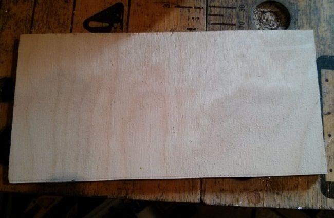
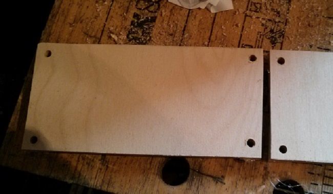
First simple step is to cut some 1/4" ply offcuts into as many 6" x 3" pieces as you need (two per cab)
then, cut four little postage stamp sized pieces per 6 x 3

then hot glue these to each corner to make standoffs (seems obvious but I forgot them on the W8's and had to bodge some in after the soldering was done....better to do it first)
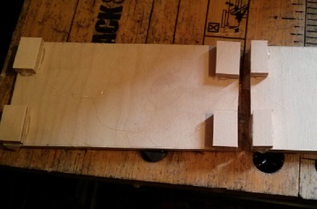
after that I drilled a 5mm hole in each standoff so I now have a blank crossover panel complete with mounting holes.
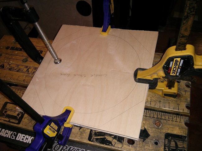
Next step was to take the various components, that I obtained from Leland months ago, loosely lay them into their approximate positions and scribble a little pencil mark to indicate where each of them sits.
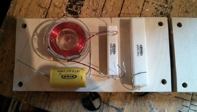
Then since you should still have the drill handy, put some 5mm holes either side of each component's location so that you can put a cable tie round each component as you build.
After that, the Spidey fun can begin, squeezing a bead of hot glue underneath each piece, press each component down onto it's bed of glue then tie it down tight with a cable tie...
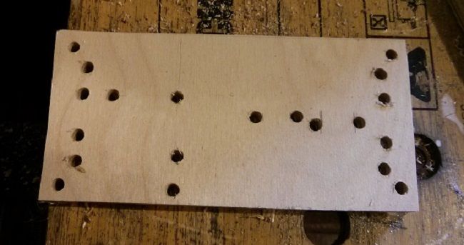
you can see in the above pic that I also drilled a smaller 3mm hole where each component lead needed to go. At this point I was called away and didn't take any more interim pics, but I kept on going with the component placement, gluing and cable ties until all the components were physically mounted. It was only after I had got all my components tied down that I got the soldering iron out and soldered each connection - you may prefer to solder as you go.
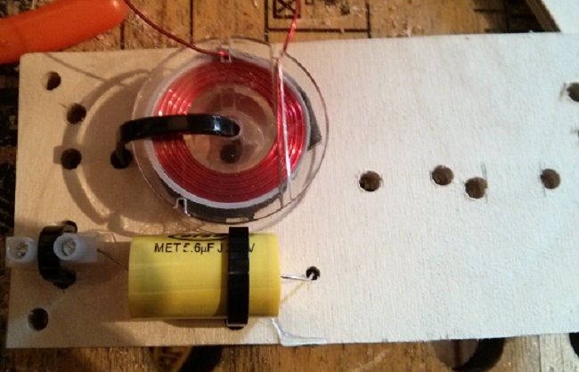
And I ended up with a finished high pass filter - don't worry folks...the 4 ohm resistor is wired in series, even though it's physically in parallel

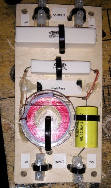
The final stage was to put a blob of hot glue over some of the pieces of wire that form parts of the +ve and -ve rails so that they don't come loose or rattle with vibration, and since I'm going back to other parts of the build now, such as doing the rest of the woodwork and making some melded arrays, it'll be a week or so until I come to mount the crossovers and my pea brain will have forgotten which way round the connections are without referring to the plans...so I got my Dymo labeller out and stuck a few labels about as reminders; should save a bit of time when installing them.
After that, you just rinse and repeat until you have them all done...the low pass filters only have two components, so they're a little bit easier, and the topography of my low pass layout is just a very literal translation of the circuit diagram onto the board...
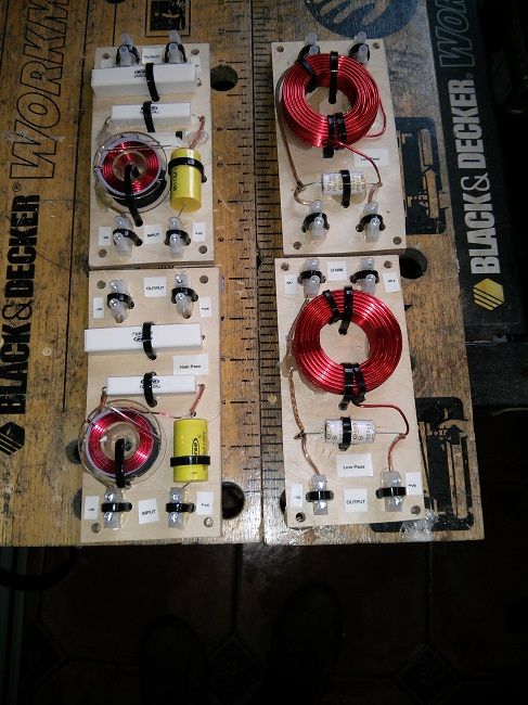
I know both high pass and low pass inductors are in the same orientation, but since I intend to mount the boards on either side of the cab there will be enough physical separation that they shouldn't interact.
OK...time to get on with my build now so "up, up and away".....Oh damn, got my Superheroes crossed over again...