Stu
Spelling Death for WLE Piezos... A Tweeter Comparison
-
Strapping Young Stu
- Posts: 1016
- Joined: Sat Dec 30, 2006 7:01 pm
- Location: Dorset, UK
-
Strapping Young Stu
- Posts: 1016
- Joined: Sat Dec 30, 2006 7:01 pm
- Location: Dorset, UK
Ok Front of the diaphragm

And the Rear - sorry I cant get further inside, that would mean having to break the thing apart


Side on so you can see the bulb better
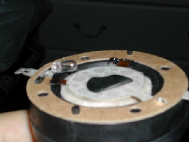
Finally with pressure from underneath the diaphragm with my finger and then without - showing the xmax if you will.


I said it was complicated, between the physical diaphragm and the piezo "cone" is a small amount of pink coloured wadding which appears to help with dampening the cone.
This is the only thing I can think of that you might be able to do to mod the piezo to maybe improve the sound.
If the bulb and capacitor had anything written on them we might be able to get some results for modding a protection circuit but there isnt anything, and I have looked with a microscope
Stu
And the Rear - sorry I cant get further inside, that would mean having to break the thing apart
Side on so you can see the bulb better
Finally with pressure from underneath the diaphragm with my finger and then without - showing the xmax if you will.
I said it was complicated, between the physical diaphragm and the piezo "cone" is a small amount of pink coloured wadding which appears to help with dampening the cone.
This is the only thing I can think of that you might be able to do to mod the piezo to maybe improve the sound.
If the bulb and capacitor had anything written on them we might be able to get some results for modding a protection circuit but there isnt anything, and I have looked with a microscope
Stu
Piezo Mods??
Thanks mate!!
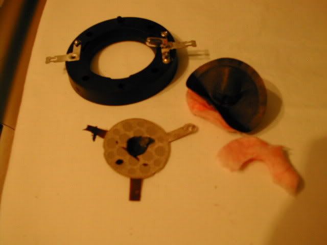
So there is an initial layer covering and extending outside the perimeter of the actual crystal. What does this material feel like?? Should be rubber like.
Then there is another layer on top of that one which seems to be perforated with large holes and provides one of the three point suspension. Then it seems the two flat wires to the piezo are also acting as two of the suspension points. Is this material conductive and does it play any role in the electric contacts of the piezo crystal?. This perforated layer may be the felt like material used to change the chamber freq and prevent power loss in the lower freq of the piezo. Have no idea what that silver disc on top of everything is for. Possibly additional weight to improve crystal to diaphragm weight ratio for more output.
Is the size of the piezo crystal in these more powerful CTS models the same as the cheap piezos? And one final question is the output of the powerline models the same as the other non powerline CTS/Motorola piezos?
Please comfirm my impressions of the pictures... let me know if I am wrong on something.
The "cap" is actually a PCS resistor see my earlier note...Can you measure resistance values across its terminals? This circuit should be able to be copied or redone with similar components.
From what I see and have read I think there is a good chance of modding these cheaper piezos for a flatter freq response and more output in the lower freq range. Will look into wether the piezo material on this cheaper piezo is as good as the CTS/Motorola stuff.
Will look into redoing the protection circuit and try modding these and report back eventually
-
Strapping Young Stu
- Posts: 1016
- Joined: Sat Dec 30, 2006 7:01 pm
- Location: Dorset, UK


Powerline piezo
Hello Stu:
Sometimes we must destroy prior to learning.
So this is just like the original motorola patent 3786202 (check it out in Google patents)
Felt or fiberglass? insulation material between the diaphragm and the piezo. Is it glued to the diaphragm or piezo or just floating in between the two? Then the piezo crystal which to the back of is applied a rubbery/neoprene like material to tame freq peaks at 1K, 5K and to some degree also 19K. This thin rubbery material exceeds slightly the diameter of the piezo. The added weight gives more SPL at the 2-3K as well as a flattened response. It appears as if the front of the piezo is also covered with similar material? The three point suspension probably adds little but wont hurt to copy.
Looks like we can copy this...only thing if the quality of the actual crystal is much different we won't get the same results. It does "look" as if the powerline piezo crystal is different from the cheap piezo. Is it bigger?
You can restore your powerline piezo...just replace the damaged diaphragm with one from the "cheap" piezos.
-
Strapping Young Stu
- Posts: 1016
- Joined: Sat Dec 30, 2006 7:01 pm
- Location: Dorset, UK
Re: Powerline piezo
1) The patent on the back of the tweeter casing is 4864624rafaro wrote:Hello Stu:
1) So this is just like the original motorola patent 3786202 (check it out in Google patents)
2)Felt or fiberglass?
3) Is it glued to the diaphragm or piezo or just floating in between the two?
4) Then the piezo crystal which to the back of is applied a rubbery/neoprene like material to tame freq peaks at 1K, 5K and to some degree also 19K. This thin rubbery material exceeds slightly the diameter of the piezo. The added weight gives more SPL at the 2-3K as well as a flattened response. It appears as if the front of the piezo is also covered with similar material? The three point suspension probably adds little but wont hurt to copy.
5) Looks like we can copy this...only thing if the quality of the actual crystal is much different we won't get the same results. It does "look" as if the powerline piezo crystal is different from the cheap piezo. Is it bigger?
2) Fibreglass
3) Glued
4) I dont think its neoprene - the piezo "wafer" is sandwiched between two layers of synthetic metallic type circuit boardy material which is obviously conductive since it is what is attached to the terminals of the tweeter. There are circular holes as you mentioned before cut in it through which you can see the wafer within. There is also that metallic foil sticker which as you point out is quite heavy.
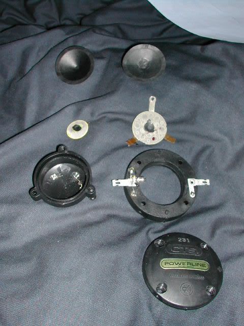
5) Yes much bigger the wafer is 32mm in diameter vs 20mm in the WLE Piezos, this is probably going to have rather a large impact on the performance.
Here is a pic of the insides of a Powerline vs the insides of a WLE - just to show the element size and that there is MUCH more to the powerline internally.
Stu
powerline piezo
Powerline piezo series were 2K Hz designs therefore the bigger sized element and longer path. Likely the cone on the powerline is heavier than cheap piezo but if same size some coats of lacquer may allow replacement of damaged powerline cone with cheap cone Will study patent 4864624 carefully. It is the actual overload protection circuit patent of year 1988.
Also noted is patent 4078160 which seems to be the bender dimorph crystal suspension and damping used in the 2 KHz piezo.
For now if you could measure the bulb resistance with an ohmmeter that would help. Just one ohmmeter terminal on the center and the other on the screw part of the bulb.
We should be able to apply the same damping /suspension principles to the regular 3K Hz piezo tweets and adapt the overload protection circuit as well.
Too bad you don't have a CTS 3 KHz piezo to see the innerds on that critter. Does the CTS 3 Khz units have the same output as the powerline 2 khz ones. Doubt it?? Does it have the same output/quality sound as the cheap piezo. Doubt it? CTS piezos have been fine tuned.
Preliminary looking into the actual crystal reveals so called high density 99.5% vs lesser density 97.5%. Likely all piezo tweets will use the high density stuff. Also have temperature voltage and "hardness" factor all which play a role in power tolerance. But for us we have to presume manufacturers pick the best combo for maximal performance.
Be back soon
-
Strapping Young Stu
- Posts: 1016
- Joined: Sat Dec 30, 2006 7:01 pm
- Location: Dorset, UK
Hey thats about as far as I am able to go with it, I dont have an ohmmeter nor know what it is or where to get one, and apart from this I wouldnt ever use it!
I hope you manage to sort out whatever you need to with it, but I am quite content to use the tried and tested method of just using lots of elements to give me high sensitivity and high power handling.
Stu
I hope you manage to sort out whatever you need to with it, but I am quite content to use the tried and tested method of just using lots of elements to give me high sensitivity and high power handling.
Stu