Re: Are 24 x T60-LAB15s Enough? ;)
Posted: Tue May 21, 2024 9:24 am
Price dropped on the K410's. 3 or more now $830 each. Saves another $100 on five of them.
Admark K410 at VIP Pro Audio
Admark K410 at VIP Pro Audio
Loudspeaker Design
https://billfitzmaurice.info/forum/
If it moves, it creates heat. The best cooling is with it offWould it work just as well (if not better) to use a different cooling tactic? For instance, since the drivers cool themselves with movement of the cone, what if we took advantage of that? Instead of just turning them off, we could have a preset that is a much lower voltage and different bandpass? So that the driver has high excursion/movement at just the low frequencies, maybe 30-40Hz, and low power, maybe 10v. So maybe it would cool itself more than if it were just off? I don't know, just a thought I had.
The frequency response chart doesn't tell you how much voltage the driver may safely use at any frequency. Knowing how much voltage a driver is safe with at a given frequency and filter slope allows one to know how much lower the crossover frequency may be taken with a higher filter slope without exceeding the driver voltage limit. Also, the 2kHz high pass filter is 24dB, not 18dB.For instance, in the Eminence ASD1000 sheet, it has a usable frequency of 2,500-20,000 Hz. It's frequency response chart clearly shows decent output below 2500Hz, all the way down to about 1500Hz, where the line starts dropping hard, and where the impedance line spikes around 1200Hz or so. But using the 18db/oct slope, the plans call for a 2,000Hz crossover. I'm feeling around in the dark here, but using a 12db/oct slope would mean that driver would go from 104db at 2kHz to 96db at 1kHz, yes? 96db just happens to be what the chart shows at 1kHz. So using the 12db/oct slope could work, but it would be riding the line? Risky business, yes? The 18db/oct ensures it is under that line the whole way, helping to protect the driver, yes? And also probably sounding cleaner, less distorted. Does that seem right?
Pics, or it didn't happen!
Cheese and Rice! You weren't kidding!Buckle up, fellas, this is going to be a long one!
60A per phase will be more than enough, which is great! I'm happy to hear you're running 6awg to the amp rack. How long of a run is it from the gen set to the amp rack? 5 wires?That circuit has a 60 amp (per phase) breaker on it, and the cable has 6 awg copper THHN (per phase). The ampacity chart shows 75 amps (per phase) for that wire. Which should be plenty of headroom, even if we don't bury the cable and it sits on the surface and bakes in the sun. Granted, we will also be running maybe an additional 5000 watts for AC, the tops, and other stuff in that area. But still , plenty of headroom for all that as well. Yes?
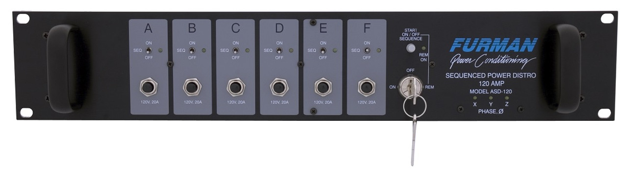
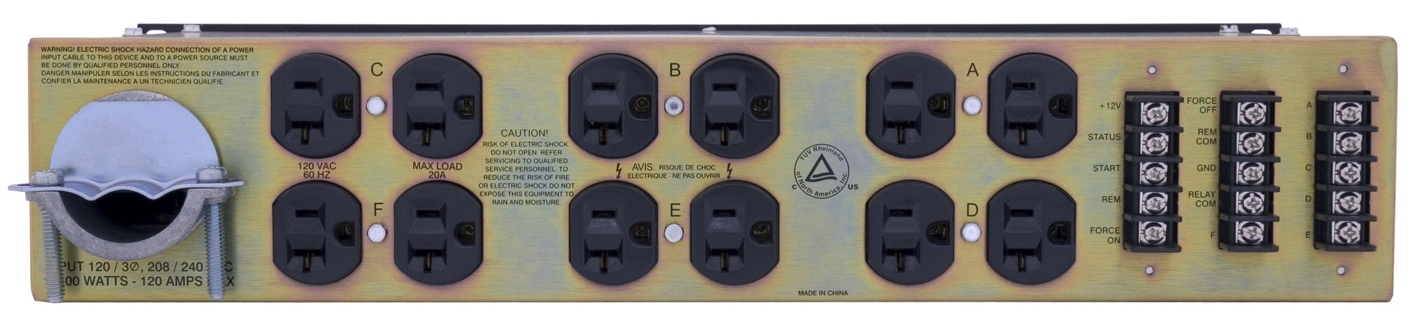
In it's current form, you're right. It wouldn't matter which voltage/configuration you used, it's all the same. I did a little research on the Furman ASD-120. It's not a power conditioner. The power comes in, to a circuit breaker, to a relay, then to the plug. It's a sequencing power distribution unit, turning on each of it's 6 circuits on in sequence. Which is cool from the standpoint of being able to leave all the amps, crossovers, mixers, and other related gear power switches in their on position and the sequencer will power them on in a sequence that keeps pops and clicks from blowing drivers as well as being able to power everything up and down with a single switch. It even powers down all the gear in reverse sequence. However, as it's delivered in stock form, even though it can be powered by 208V 3 phase power, there's nothing inside of it that is 208V, zero. It's completely 120V. Each leg and a neutral goes to 4 receptacles, totaling 12 receptacles on the back of the unit. Power wise, it's essentially the same thing as running three 120V extension cords from the generator, wired to different legs and all loads would be calculated based on 120V. That said, it can easily be made to work at 208V, which does have a considerable effect on the rest of the grid. More on that in a sec...Also, I agree that if we can minimize amp draw on the power grid, that is a good thing. I am just saying that with our usual setup, using a Furman ASD-120 power conditioner, it won't really effect the rest of the grid whether we run 120v or 208v or 240v. This is because the Furman will take the 208v from the generator, and then split it into 6 x 120v/20 amp circuits. So the power delivered to the Furman will be at a higher 208 volt, and a lower amperage draw.
I love the creative thought process! There's an easier way that's also way more clean and elegant. To get 208V at any of the output jacks, all you would have to do is find the two black wires on the "X" input terminal labeled "A" and "B", follow them to the relays they're connected to, then trace the white wires from those relays back to the Neutral input terminal block, disconnect them, and move them to the "Y" terminal. For "C" and "D", the whites should be moved from Neutral to "Z" and for "E" and "F" move the last two whites left on the neutral input terminals to the "X" terminal block. Then every outlet would be wired 208V. A and B on PH1, C and D on PH2, E and F on PH3....maybe I could do something crazy like cut 2 cords coming off two different Furman outlets (with two different phases) to get 208v back from the 120v? Wire the two hots, merge the grounds and then wire them in, and just cap the neutrals and leave them out of it? That way we could get the 208v, and still use the other Furman outlets to power the other 120v devices?
Yes, 9500 is correct.As a complete system, though, at 250w per T60 and DR280, we'd be at 32 + 6 = 38 x 250 = 9500 watts, not 7500, correct?
57A total, split three ways, 19A per phase... if there was a way to split 4-5 amplifiers equally into 3 circuits.9500w/80% = 11,875w/208v = 57 amps from the genny to the Furman. (Could be more with a little voltage drop and increased resistance in cable due to high temps. We'll crank the voltage up on the genny to compensate, though.)
Granted the amplifiers probably wont use 20A in use, that's awfully close with little to no buffer based on maximum potential draw.11,875w/120v = 99 amps from the Furman to Admarks. (Need to use 5 x 20 amp circuits, 1 Admark per circuit.)
Tat's a fair call. I wouldn't be surprised if the DR's take close to that.11,875w x 80% = 9500 watts from the Admarks to the drivers.
9500w/45v = 211 amps to drivers. (Just treating the DR280s the same as the T60s for math simplicity.)
No. There is no standard rating voltage. There is rated power at an impedance load. In the case of the K410, it's 2890W per channel at 2Ω. To calculate what the voltage is into a 2Ω load to result in 2890W... The square root of (watts x Ohms) = volts. 76 volts in this case. Where at 8Ω and 1000W, it's 89V. 82V at 1700W and 4Ω.If the Admarks can do 2890 peak watts per channel at 60v (which is the standard rating voltage, correct?), then 2890w/60v = 48 amps per channel.
10.5 amps/48 amps = 22% of capacity
I would absolutely, no doubt in my mind, wire the Furman up for 208V from the get-go....so...
Easy peasy, lemon squeezy! 120v all day long with 5 amps, right?
And if shit hits the fan, we can McGyver 208v off the Furman 120v outlets, and really load up the Admarks.
He claimed it was at full tilt, maximum power. Still, I would personally only use the information as a indicator and still plan your system power based on maximum potential.If Corona Operator had 800w peak, which would average to 100w peak per cab, then we'd have 32 + 6 = 38 x 100w = 3800w, right?
But I also feel like he could have his cabs turned way down, because he is likely indoors?
Technically, you could push the amplifier to the edge of it's capabilities. For a small DJ rig that runs a couple hours at a time in average ambient temperatures, give it a go and see if the amp remains cool enough to stay out of any protect modes. In a high heat environment, four Admarks on subs would be fine if you're able to keep them cool. If you ran 8 Admarks on subs, you may not have to worry about cooling the amp rack with AC, they're rated to be used in temperatures up to 113ºF. I would still recommend running the Admarks on 208V.Maybe, using all this, that means that two Admarks can run 16 subs each, with each Admark plugged into its own 20amp/120v outlet on the Furman... If any short blips can sneak through without tripping the breaker, and the capacitors in the amp can handle the 45v peaks, yes? Otherwise, using 4 Admarks on 4 outlets would be just fine, yes? Any more amps than that would just be further insurance?
It's really hard to make broad generalizations about this. Every amplifier model will exhibit it's own characteristics, no matter the baseline technology.But also, and probably more importantly, the advantage of modern class D amps have higher peak capacity, yes? My guess is that they have more/better capacitors, and all of that good stuff, inside that can provide the higher peak capacity. Does this seem correct? Plus, if they have integrated DSP, all the better. But really, if they have one single major advantage, it's really all about the peak capacity, correct? Because music reproduction and amplification is so inherently transient? Meaning continuous ratings fall more in the category of fancy hubcaps?
Two cabs wired parallel will present the amplifier with half the impedance of just one cab. Half the impedance results in twice the power (watts).All that said, I am puzzled by how the series-parallel harness would work. As in, if I make a harness myself, how exactly would it work, given the T60s will be wired in parallel? Or would it be easier to take off the speakon dish and adjust at the terminal blades? I feel like once I see the answer, it will seem so simple, and I'll just shake my head at my own stupidity!
The main contributing factors of amplifier heat are the impedance of the load and ambient air temperature. Lower impedance, more power, more heat. Elliot's recommendation to use no less than 208V on that particular amplifier has nothing to do with amplifier heat and is purely based on being able to get enough amperage to the amplifier and minimizing voltage drop. While testing only one of the two channels, he measured inrush currents of 37.86A at his testing supply voltage of 250V. At 120V, that would be 78.9A, or 157.8A with both channels run. No matter how short the blip, 158A is a buttload of current to try and pull out of a 15-20A wall socket, let alone one of three legs of a generator.I think that means the Furman and amp will create more heat within themselves as they work with the lower 120v instead of 208v. And maybe that is what Elliot's testing indicates - that 120v creates too much heat and that it has a harder time performing at full output. But, if we aren't running these amps anywhere near 116v, then using 120v/20amp outlets instead of 208v or 240v probably doesn't matter. Does that sound plausible at least?
When playing a sinewave (I usually use 60Hz, but 50Hz should work fine too) you should measure constant voltage at the amplifier output, no fluctuation. What were you playing to set the voltage? It could be your source material wasn't constant amplitude, maybe. If I am tuning a system that doesn't have a built in oscillator, I usually use Onlinetonegenerator.com.We are really starting to lean hard into the newer class D amps. Here's why.
One thing that has changed since I last posted, is that we attempted a A/B comparison of the Macrotech 2400 and the Itech 5000 amps that we have. Emphasis on "attempted". You might remember that we only have 2 working T60LAB15s from our once mighty count of 12. So, we hooked up one on each channel of each amp.
First, we took a multimeter to the output of each amp to set the limiter, so that it would be roughly 55v. (The plans say max 60v, and we backed it off a little just for a safety margin.) This process felt very clumsy, though. The meter jumps all over the place. That makes sense because it is producing a sine wave, yes? So we tried to dial it in by splitting the high and low values that would flash on the screen. We figured seeing 60 ish volts on one flash, and 50 ish volts on another meant we were close enough to a 55v average. We decided that we should get an oscilloscope to make that process more exact. Thoughts?
By "clip", do you mean when the limiter kicked in? Or, were the amplifiers indicating they were clipping? They definitely shouldn't have been clipping.We then listened to a continuous 50Hz sine wave on repeat, walked all around, and tried to get a good impression of the sound quality, while changing volume levels from low all the way up to clip. Then, we stopped, unplugged the speakers, plugged them into the other amp, and listened again. Back and forth a few times.
The amps were not balanced. If they were, you wouldn't hear anything different between the two. You set each limiter separately on different outputs, correct? After that, check the voltage at one amplifier output, then connect the voltage meter to the other amplifier and adjust the output gain in the Driverack on that channel until the voltage is as close as possible to the first measurement.We realized that it's tough to get a really good comparison without an immediate switch back and forth, like Dave Rat did in his amp comparison video. It's hard to tell by memory alone! The only thing that really stood out was volume. It seemed like the old Macrotech was quieter. That could have been due to a number of factors, though. Like maybe we didn't have the limiters set exactly the same, to deliver the exact same voltage from both amps. Maybe the Macrotech was sending slightly lower voltage, and that accounted for the lower volume. Also, we didn't have a decibel microphone. It was just noticeably quieter.
Neither of these amps should have been anywhere near clipping. The limiter should not have allowed the amps to clip. My guess is the "wah" sound was the driver being pushed past it's designed operational limits, well past xMax.The other interesting thing was that at clip, the Itech was much cleaner. Didn't even flinch. The Macrotech, on the other hand, started giving a distinct "wah wah" sound when near or at clip. Is that what harmonic distortion sounds like? It didn't sound good. Maybe it's just the case with this one amp, and doesn't speak for the group as a whole? Either way, it made me really glad we tested. It wasn't just a audiophile level of subtlety, either. It was VERY obvious.
Sinewaves wont tell you squat. Gotta play music to hear anything discernable, which I highly doubt you will. Do you guys have tops with you when you're doing this? If not, I'd recommend it.We are hoping to do a better test this weekend. We will use a dbx microphone this time. (We forgot it last time.) The hope is that if we can make sure each amp is producing the same decibel level, we can get a better feel for if there is any "color" that old Macrotech has vs new Itech. See what this whole "rolling bass" vs "punch" might actually sound like. And if so, whether it is desirable or not. Also, maybe we need to play actual music instead of just a continuous 50 Hz sine wave.
- Disconnect speakersDo you guys have any suggestions on this process?
Maybe any clever tricks to get that instant switch back and forth between amps, so the difference would be immediately heard, rather than relying on short term memory?
Do not run them stereo. The frequencies aren't directionally locatable so there's no point. You could blindfold someone and put a clean playing subwoofer a foot away from one side of their head, aimed directly into their ear, play music for them, ask them to point to the subwoofer and they'd either not be able to say where or point somewhere in front of them in the general area of where the mains are. The exception is subwoofers that have a lot of harmonic distortion, which occurs at frequencies that are directionally locatable. I still wouldn't run them stereo.what is the advantage of running mono vs stereo for the subs?
I'm not sure about the need for delays at those widths. My gut is telling me the taller narrower stack will have better mutual coupling, higher sensitivity, and more available peak output. Although, testing will likely be the only way to know firsthand which tradeoff scenario better fit's your sound goals and deployment limitations.On that note, the tightest, most dense deployment it seems like we can practically do is 2 cab high (upright) x 16 wide, or 3 cab high (on their side) x 10-11 wide. So that would be about 62" (2 x 30" + rubber feet) or 5 ish feet high x 324" (16 x 20" + 1/4" spacing between cabs) or 27 ish feet wide for upright. Or 63"/5' high x 334"/28' wide on their sides. We probably don't have any need for delays or fancy stuff with those "tight" dimensions, correct?
I like the "sound" of that. (very punny, ar ar ar)Back to driver temps and sun exposure for a bit...
The cabs in the center will be shaded. So, if we go for a tall/narrow deployment, they will all be shaded.
One thing you have going for you in this regard is, the cabs won't be black.If we go short/wide, several might be in direct sunlight all day long.
But will the shade in that location be much more beneficial? Maybe, maybe not.
This is just a wild guess, but I'd wager a medium sum that more thermal transfer occurs through the driver cone than the 1/2" thick wood box around the driver. In which case, I'd think airflow would be sufficient around the cone area just from using it.It's likely that we will do 2 rows of 16, upright (not on their side). If they are all tucked in a nook underneath the DJ booth, they will be out of the sun. Good. But there will not be great airflow... Bad. Maybe sixes inches above the top of the top subs, a quarter inch or something between subs. Potentially much more room off the sides, but still it would be a nook. Maybe we open up the sides of the nook for better airflow...
Anyway, the point is that airflow can make a huge difference in temperature, for sure. Is it better to be in 100 degrees, full sun, and 10 mph wind? Or 100 degrees, shade, no ventilation? Maybe we should try to have a few box fans in the nook? As well as leave the sides open?
$12, almost 11,000 reviews, 4.5 starsBy the way, I love the idea of wireless thermometer! I think I'll get a couple if the price is right! I would be great to monitor in real time! And make adjustments if necessary!
You can put them any way you like. A stack of four, each in a different orientation, would perform the same as if they were all uniformly oriented. No downsides to any particular orientation.Given this application, does it matter whether these cabs are on their side, or even upside down?
Would there be any danger of driver sag, or something like that, if they are playing almost nonstop, for a week straight?
In other words, is there any reason not to only have them upright?
Screws are the preferred driver mounting solution. Bill has mentioned that he likes to use roofing screws, designed to screw down metal corrugated roofing panels into plywood. They have a hex head which means you use a socket to drive them, and less chance of a driver puncture than a Philips screwdriver if it happens to slip and come in contact with the cone. You're gonna need 304 screws (8 per driver, 38 drivers), here's a box of 400 #10 x 1.5"We are planning on mounting the drivers with wood screws. I've had a gander at charts with shear strength, and withdrawal strength, and it seems like we'll be just fine from those perspectives when securing the driver frame to the cab. I am just not sure about the the rest of the driver components. Will yes be okay good okay?
This decision will also save you a buttload of money. 64 castors would easily set you back another thousand. For budgetary reasons, money better spent on amplifiers... and a hand truck. LOLAlso, after agonizing about where to put the casters and feet, we finally made a decision! So that we can easily change the configuration of the subs, we ultimately decided to do NO casters, and only rubber feet.
Also a bit of a time saver in the build process. I'd personally put some in the back behind the reflectors with the quarter round behind. But, it is an extra detail step that could save many hours for this many cabs if skipped.I tried just using a regular ole dolly to move around one of our T60LAB15, and it was just fine. A mere mini fridge. So we'll just use regular ole dollies. The side benefit of that is we don't need hand hold cutouts. I suppose we could go without them even with the onboard casters, but meh. The point is, that several of the cutouts in on our old T60s have split/cracked because of people dancing on them or lifting them onto the trailer. Plus, if we flip the subs on their sides or upside down, and there are no cutouts, then there are no trip hazards at all in any of the orientations.
The placement rules are good for all subwoofer designs. Placing direct radiators next to each other and/or stacking will still result in +6dB increases per doubling, but only horns will get flatter response and increased extension with additional cabs.I've gone through the "Rules for Subwoofer Placement and Stacking"... ...Do these rules apply to all subs? Not just the Titans pictured? The answer is yes, I'm pretty sure. But I can't explain why.
The inherent design of the Titans, with the mouth on the side create additional horn length as well as increased mouth area when stacked in a "V" configuration.I see that in the Titan plans, the triangular "V coupler plate" is included right in there, in the plans, towards the end. However, in the T60 plans, there is no such mention. Only references to boundary loading, cancellations, corner placement, etc.
Why is the V coupler not in the T60 plans? My guess is because if we put them all in a row, they already couple, yes?
I assume this is meant to say Tuba. Tuba 45 and Tuba60, with their end firing design have nearly nothing to gain in the way of horn length and would actually have reduced mouth area if they were used in a "V" configuration. The other Tubas can be used in a "V" configuration and V-plated.But can't we also do that with the Titans?
Not with the T60 and the benefit is also moot given your cab count. I think Bill says with 8 Titans the V-plate no longer offers additional sensitivity.So is there an additional advantage of doing the V coupling? For an extra 3db for free? Or would you only bother with the V coupling if you only have a few subs, and don't have, I don't know, 32 or so cabs?
If you can gain the 3db, is it an option that we can consider the V coupling with the T60s? Is an extra 3db for free possible in this situation?
I love the thought process. I've had similar thoughts. If there was anything to make them better, I'm confident Bill would have put it in the plans or one of the sticky threads. I think your best bet for maximum output potential and maximum mutual coupling is to do one stack as high and narrow as you can.What if we can build our DJ booth, and position the T60s, in a way that effectively creates a mega V coupler and/or elongates the horn? We could build our own kind of corner placement, or maybe even better than a corner, with V coupling as well? Generally speaking, maybe we could build what amounts to a further extension of the horn path in the T60? Or would that matter at at all, given that the 20" max width cabs would already horn load all the way down to 28Hz (or however far, I forget)? Does all this sound just plain dumb dumb stupid? I'm like 50/50 on it. Or maybe 80/20. 80 being that it does sound dumb dumb stupid. 20 being it's sounds only dumb stupid.
A boundary needs to be at least one wavelength radius from the position of the subs to achieve the full 6dB gain of going from half space to quarter space. So, for 25Hz, you'd need to be centered on a wall (yes, high density. The more dense, the better) 90 feet wide by 45 feet tall. 45' wide, 22.5' tall for 50Hz. Boundary loading is more of an indoor technique, although I would boundary load on any wall I had outdoors, just 'cause... better than not and also eliminates any 1/2 wave cancellations in the higher frequencies if aimed out from the wall.Also, what exactly is considered a boundary? My guess is it would be something capable of reflecting all the sound energy, rather than allowing it to reverberate and pass through. What enables that? High density/mass?
And I'm also guessing that the definition of a boundary is different depending on the frequency... lower frequencies need more boundary-ness, yes?
For the sub 100Hz range, would a shipping container count as a boundary? Would a plywood wall/reflector count? Linking this back to the V coupler questions above, can we be clever with the subfloor design of our DJ booth to create even more horn loading?
You'll have to listen to it in person to really know. You may have shit your pants performance in any configuration and not need the maximum output potential. If it fit's your camp vibe more, you could put the wall of subs completely out of site, behind the DJ booth. Whether it's under their booth, behind, or anywhere else, they're gonna get the crap rattled outta their brains. Put the sub wall out front, drape canvas over it, have cans of paint nearby, and encourage people to paint it... an ever changing mural wall that can be sent to the burn. Just throwing ideas out there. But really, you're going to have to give your DJ's short set times or frequent breaks. Although, maybe you'll get one that's a true bass head who wont leave. LOLOur First Option of Deployment (as of now, anyway) - "Max Output"
If you go back to the pretty picture of the gold standard art car, we figured we'd use that as inspiration for our "max output" configuration.
We talked at length about doing something more dense, such as 4 high (on their sides) by 8 wide, for a roughly 7' x 20' cluster. (How crazy would that be, btw? A whole wall of T60s!) However, it just doesn't seem to fit with the vibe of our camp. Maybe we can be persuaded otherwise, but it will need to be a compelling case. For instance, Seth, going back to your 3x5 and 1x15 models, it seems like our 5'x27' would be close enough 7'x20' (the max 3x5 model) without giving up too much output, yes? Maybe only 1-2db?
You could very easily have an alternate DJ booth at ground level for the times when the gathering is small and the volumes are down.Okay, okay, I know. I hear you. This whole time I've been saying sound quality over aesthetics, and I'd like to think I've stayed the course, even when difficult. But, I think we've reached the limit on this front. Having the DJ be up 8'+ off the ground is just too much for us. At least too much for now. I've floated the 8'+ idea, and there have been strong objections. We need more "accessibility" to the DJ. I know it's just 2' of difference between the 6' and 8'+, but 2' can be a lot, right? Especially during smaller parties? Just think of a guy that is 2' taller than you. Damn near breaks your neck to look up that high, right? Also, doing this will put our DJs at the same height as the gold standard guys. Having experienced it, I can say that 6-6.5' height is plenty high for a DJ focal point for the audience, as well as experiencing low frequency output. The difference is that the top of their subs is at 6', because the deck of the vehicle is about 2.5' off the ground. Our subs will be right on the ground and come up to 5'. That probably doesn't make a whole lot of difference, but I thought I'd mention it anyway.
I'd certainly take note's about any system configuration I heard and highly liked or highly disliked. However, I'd try to focus less on what they have and more on what you have. You'll likely at least match their volume, have way more extension than they do, and could potentially be a cleaner sounding rig than theirs. You're going to be very proud once it's all set up, tuned, and pumping out amazing sound quality at more than sufficient volumes.They have basically a 4' high x 24' wide array of subs, that is about 2.5' off the ground. Their J-arrays are just on the outside of that, with the lowest edge of the lowest cab at about 6.5-7'. This is a proven, gold standard concept.
The B2 is rated 600W RMS/300 per driver. Do they feed them more? Dunno. Keep in mind the next 3dB will cost them another 600 per cab, and that 3dB assumes the driver is still within it xMax. And 3dB more than that is a smoked driver pipe dream. Either way, I hope both you and them have enough system that you guys aren't having to redline it for the bigger gatherings.It occurred to me over the weekend that, even though we have the advantage of horns, in the end, it probably doesn't matter. This is because in practice we won't be listening to either system at 1w/1m. The T60s will be limited to 45v, 253.125w. That means we gain about 24db, by increasing the power from 1w to almost 256w. However, the B-2s are not limited to 45v/253.125w. That's a big, big deal, yes?
I'm not sure how hard they can be pushed. For output in that 60Hz and below range, which it seems there can never be enough, the B-2s might have a significant advantage.
Complete hogwash. You're torturing yourself. Not my sorta kink, but you go right ahead.Since they don't have the high pressure and demands of horn cabs holding them back, that means they can crank the power levels way, way, way up, correct?
I'm not going down that hole again. Take another deep breath. Your system, set up and tuned well, is going to be outrageous.To what limit without risking over-excursion, I don't know. I'm not sure what 18" drivers they are using in the B-2s... Let's use the Eminence 18" as a placeholder, yes? They can do 1600w continuous, 3200w peak. So, if they can do 3200w peaks without over-excursion or distortion, that means they can do 160v instead of 45v. Let me say before going on, that I don't even know if that's possible. But, if I don't a little thing like "what's possible" or "I'm so, so wrong" stop me, then I can continue. If they have the amplifiers and all that that can handle it, a full 160v is probably still not realistic. So, let's take that down to say 128v. That would be 8 ohms, 128v x 16 amps = 2048 watts. Comparing 2048 watts to 256 watts, that's a 9db difference, correct? So the B-2s are about twice as loud in that "feel it" range than the T60s. If we were talking about higher frequencies, in which the extra decibels would be of no benefit, then forget it, it doesn't matter, because there is easily such thing as too loud. But we are talking about the low stuff, here, below most human ears, in which there can always be more, yes? Especially outdoors. That said, B-2s win, and they win very easily. However, it takes way, way, more power to do it! 24 drivers x 2048 watts = 49,152 watts. Versus 32 drivers x 253.125w = 8,100 watts. 49,152/8,100 = just over 6 times the power...
It is fun to think about. But, let's stay focused here.Side note, wouldn't it be something to see what an appropriately sized horn cab for these bigger drivers (18", 21", or more) can do? Assuming the drivers could survive the pressure? First of all, how big would they be? And how would they feel? I imagine it could be something crazy like rotor wash from a helicopter. That level of output probably isn't super desirable in practice, but it's kind of fun to think about, isn't it?!
I made the cab count recommendation based on the area you spec'd. If you wanted to build 2-4 more, it would certainly look cool. But, I don't think you'll need it.Any chance we dare compare 6 x DR280s to their 20 x V12s? And maybe use this to help place our DR280 arrays? How far apart, how far forward/back, how much delay (if any), etc.?
They obviously can cover a much longer distance with their V12s, much more than we'd need for our DR280s. It would just be interesting to see how the quality might compare in that first 10, 50, 100, 200 feet. Coverage beyond that, beyond 200' feet for sure, that doesn't matter to our situation at all.
Eye candy. Complete overkill for someone standing a few feet away.Oh, also, note that their DJ monitors are 8 x V8s. 2 stacks of 4, rotated 90 degrees on the deck, on each side of the DJ. What do you think of that?
I was quite confused about that too. Looking at the chart of two waveforms 120º apart just seems like it should be lumpy. However, it's not. If they were both hooked up to the same side of the load and a Neutral on the other side of the load, I'd expect the waveform to look like you're saying. But, when the two are opposed, they result in a sinewave as pure and symmetrical as the original sinewaves.I get the concept that the line-to-line sinewave is a product of the voltage potential difference at any given point. I just don't get how it would be another "pure" sinewave, instead of a highly modified, humpy kind of sinewave. I'm not disagreeing with the concept, I just don't understand how it can be the case. At the points of highest differences, the red and blue are parallel. That would create a flat-top hump, yes? Not a smooth parabola? Maybe the hump vs. parabola doesn't matter, as long as there is 208v available?
Sounds like you've got a pretty good hold on it all. Except, anything that would effect cabs "further down the line" would effect all cabs in a series circuit. One cab wont be quieter than the others.On a separate note, I guess I fundamentally do not understand the difference between the advantages/disadvantages of series vs parallel wiring.
General concepts that I get...
Both circuits use the same amount of energy. Or close enough, anyway.
To have enough juice to power multiple cabs on a series circuit, you gotta have higher voltage because there is more resistance. Your power source better be good, otherwise further down the circuit you get, later cabs will be quieter. Also, if something goes wrong at a single link, the whole chain is down. You get to save on wiring, though. Lower over lengths, and probably smaller diameter compared to parallel. Maybe that's not a big deal in this application, though, especially if we already have bigger speakon cables.
That seems like a good rationale....for this application, where we are way out there on the moon, it's nice to have backups and redundancies. So it seems like parallel is the way to go. As is having more smaller amps than fewer large amps. Same for ACs.
Yes, cab design has a huge effect on the effective usable frequency range. With subs, horn or ported direct radiator, once the frequency is below the designed frequency range of the cab, cone travel increases quickly with less and less output the lower you go. Push too hard down below and the driver's voice coil will smack the backing plate which can cause permanent physical damage to the coil.What exactly is "usable frequency range"?... ...Does being in horn cabs like the T60 and the DR280 change the usable frequency of a driver, extending it to the downside? Is that what the whole lower extension thing is about? Does having multiple cabs change it as well? If yes, is it because the horn loading and/or additional cabs allow a lower amount of energy to produce the frequency, meaning less strain on the drivers?