TESTING Your Finished Project
Is there an accepted way of testing your finished speaker(s)?
I know the industrial standard is Half Space testing with 2.83v at 1 metre.
But has there been a standard adopted on the BFM forum so that we can compare our speaker project to other peoples, as well as Bill's SPLs?
Having graphs that are easy to compare against each other would also make it easier to pin down any problems with your finished project.
Not only should we have a standard technique for testing that would be relatively easy for most builders to achieve, but also specifications for presentation of the results. e.g. axis range, smoothing, etc.
I know the techniques, presentation, etc, would change from speaker to speaker (e.g. sub or full range), but if we have a standard, then any graphs builders put up in the forum, will have more meaning, and can be easily compared to other builder's graphs.
Just saying.
-
- Posts: 6915
- Joined: Mon Nov 28, 2011 11:12 am
- Location: Ilfracombe Queensland Australia
- Contact:
Re: TESTING Your Finished Project
Since you started another thread lol.Nordo wrote:Is there an accepted way of testing your finished speaker(s)?
I know the industrial standard is Half Space testing with 2.83v at 1 metre.
But has there been a standard adopted on the BFM forum so that we can compare our speaker project to other peoples, as well as Bill's SPLs?
Having graphs that are easy to compare against each other would also make it easier to pin down any problems with your finished project.
Not only should we have a standard technique for testing that would be relatively easy for most builders to achieve, but also specifications for presentation of the results. e.g. axis range, smoothing, etc.
I know the techniques, presentation, etc, would change from speaker to speaker (e.g. sub or full range), but if we have a standard, then any graphs builders put up in the forum, will have more meaning, and can be easily compared to other builder's graphs.
Just saying.
Subs: ground plane testing ie microphone about an inch above the ground, cab bottom on the ground IIRC.
Results need to be equivalent to 2.83V/1m. You may not get a good reading at 1 metre.
So you might, for example, make it 28.3V for output, with the mike at 10m
Results should be smoothed, can't remember the value for that.
Sure it makes it easier to compare apples with apples, but really, if you can give your measurement criteria, then that can be enough to compare.
Always outdoors, with at least 17m of clear space before the nearest, well, anything, so that would include shed, fence, house, large tree etc...
Built:
DR 250: x 2 melded array, 2x CD horn, March 2012 plans.
T39's: 4 x 20" KL3010LF , 2 x 28" 3012LF.
WH8: x 6 with melded array wired series/parallel.
Bunter's Audio and Lighting "like"s would be most appreciated...
DR 250: x 2 melded array, 2x CD horn, March 2012 plans.
T39's: 4 x 20" KL3010LF , 2 x 28" 3012LF.
WH8: x 6 with melded array wired series/parallel.
Bunter's Audio and Lighting "like"s would be most appreciated...
Re: TESTING Your Finished Project
Did a fair bit of ground plane testing many years ago, when I was building speakers for my home theatre.Grant Bunter wrote: Since you started another thread lol.
Subs: ground plane testing ie microphone about an inch above the ground, cab bottom on the ground IIRC.
Results need to be equivalent to 2.83V/1m. You may not get a good reading at 1 metre.
So you might, for example, make it 28.3V for output, with the mike at 10m
Results should be smoothed, can't remember the value for that.
Sure it makes it easier to compare apples with apples, but really, if you can give your measurement criteria, then that can be enough to compare.
Always outdoors, with at least 17m of clear space before the nearest, well, anything, so that would include shed, fence, house, large tree etc...
I assume you are saying that the mic should be further than 1m away due to the size of the mouth of my T39s (and most horn designs).
Is the dB proportional to the voltage and inversely proportional to the distance - or is it logarithmic?
Or are they both logarithmic, therefore adjusting both by the same proportion would result in unity?
Not that it matters really. I'll can do different trials until I get a useable result.
Have reasonably good open areas around the house. Maybe not as good as you.
- Bill Fitzmaurice
- Site Admin
- Posts: 28646
- Joined: Tue May 02, 2006 5:59 pm
Re: TESTING Your Finished Project
SPL drops by 6dB with each doubling of distance. It also increases by 6dB with each doubling of voltage. Therefore SPL/1m/2.83v = SPL/2m/5.66v = SPL/4m/11.32v etc.Nordo wrote: Is the dB proportional to the voltage and inversely proportional to the distance - or is it logarithmic?
Re: TESTING Your Finished Project
I don't think there really is a 'standard' due to environmental conditions. If you measured exactly where Bill measured then you could compare but, if not then i think you have to estimate/compensate etc.
I'm finishing up a 2nd pair of T39s and no matter where I measure I just hope they are all, separately, the same; then I"ll be a happy camper because I'll be pretty sure that none of them is leaky or has other problems.
2X OTop 112, 3012HO, melded - 2X T39, 27", Lab 12 - XF 212 - 4 DR250, 2 melded, 2 straight
2 20" T39 3012LF - WH10 - WH8 - in the shop - 2 more 20" T39s
http://saltandlighteureka.org still need a trailer
2 20" T39 3012LF - WH10 - WH8 - in the shop - 2 more 20" T39s
http://saltandlighteureka.org still need a trailer
- BrentEvans
- Posts: 3044
- Joined: Thu Oct 09, 2008 10:38 am
- Location: Salisbury, NC
Re: TESTING Your Finished Project
You should drop practical snippets like this far more often.Bill Fitzmaurice wrote:SPL drops by 6dB with each doubling of distance. It also increases by 6dB with each doubling of voltage. Therefore SPL/1m/2.83v = SPL/2m/5.66v = SPL/4m/11.32v etc.Nordo wrote: Is the dB proportional to the voltage and inversely proportional to the distance - or is it logarithmic?
I also second the motion of a recommended test / measurement procedure. I'd be willing to write it myself for the sticky section given the specs... I know the procedure I use but having it from the man himself would bee nice.
99% of the time, things that aren't already being done aren't being done because they don't work. The other 1% is split evenly between fools and geniuses.
- Bill Fitzmaurice
- Site Admin
- Posts: 28646
- Joined: Tue May 02, 2006 5:59 pm
Re: TESTING Your Finished Project
I'm sure I've posted it before. Measure the speaker ground plane to find the 1/2 space measurement below the baffle step. In the case of a sub you're done. With a top take the ground plane first, then put the cab on the ground face up, with the mic suspended above it at least 2 meters high. Measure again. This gives the 1/2 space measurement above the baffle step. Splice the two measurements where they meet. You have to do the top this way, because a ground plane measurement will be 1/2 space below the baffle step, 1/4 space above it. You can't measure a top with the cab horizontal with the mic on axis either, as that will introduce a ground bounce response notch.BrentEvans wrote: I also second the motion of a recommended test / measurement procedure. I'd be willing to write it myself for the sticky section given the specs... I know the procedure I use but having it from the man himself would bee nice.
Re: TESTING Your Finished Project
I'm getting a bit lost here.Bill Fitzmaurice wrote:I'm sure I've posted it before. Measure the speaker ground plane to find the 1/2 space measurement below the baffle step. In the case of a sub you're done. With a top take the ground plane first, then put the cab on the ground face up, with the mic suspended above it at least 2 meters high. Measure again. This gives the 1/2 space measurement above the baffle step. Splice the two measurements where they meet. You have to do the top this way, because a ground plane measurement will be 1/2 space below the baffle step, 1/4 space above it. You can't measure a top with the cab horizontal with the mic on axis either, as that will introduce a ground bounce response notch.BrentEvans wrote: I also second the motion of a recommended test / measurement procedure. I'd be willing to write it myself for the sticky section given the specs... I know the procedure I use but having it from the man himself would bee nice.
I think you're saying that conducting Ground Plane testing for subs like the T39, "baffle step" can be ignored because :-
1. We would only be interested in the results up to say, 200Hz.
2. Most horn loaded cabinets have no real baffle.
However, due to the size of the horn mouth, would you tilt the cabinet forward to aim the axis at the mic? Or wouldn't it matter due to the low frequencies being used?
Also, for subs only, would Near Field testing be an option? This would make testing easier, and help provide uniformity to individual builder's submitted results.
I understand that testing mains (or any speaker that has useful response above 200Hz) would need to take into account the baffle step.
When I was building my home theatre main speakers about 20 years ago, I can't remember doing a half space test, but I do remember adding a compensation circuit in the crossovers to compensate for the step.
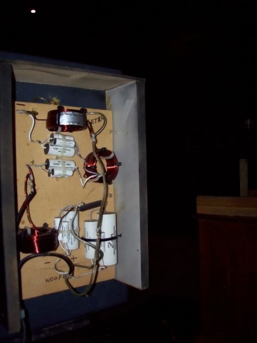
Twenty years on and still going strong.
The speakers were a closed two way cabinet. I built the speakers, carried out the testing, then designed the passive electronics (mounted externally) to provide the crossover and smoothen the response, whilst trying to keep the phase in control. Very challenging, but very satisfying result.
- Bill Fitzmaurice
- Site Admin
- Posts: 28646
- Joined: Tue May 02, 2006 5:59 pm
Re: TESTING Your Finished Project
That. The baffle step takes place where the baffle is a wavelength in dimension. At 200Hz that's 5.6 feet.Nordo wrote:
I think you're saying that conducting Ground Plane testing for subs like the T39, "baffle step" can be ignored because :-
1. We would only be interested in the results up to say, 200Hz.
Below the baffle step frequency radiation is omni-directional. That's why you get a half-space result with it on the ground.However, due to the size of the horn mouth, would you tilt the cabinet forward to aim the axis at the mic? Or wouldn't it matter due to the low frequencies being used?
With a large speaker the result will be corrupted by the presence of the cabinet itself. That's why measuring from at least two meters out is preferable.Also, for subs only, would Near Field testing be an option? This would make testing easier, and help provide uniformity to individual builder's submitted results
Re: TESTING Your Finished Project
OK.
Can someone with a bit more knowledge than me, write a sticky (in plain English "for dummies") which can recommend testing procedure for our BFM projects?
e.g. For Subs - Ground Plane on a non-vibrating surface (concrete, bitumen, min area needed,etc); 2m mic distance; 5.66v; 1/6 smoothing; suggested testing equipment/software; etc
And perhaps suggested presentation format - axis limits, etc.
Then a separate protocol for Mains including detailed procedure for ground plane and half space testing and how to combine them, as well as the rest of the procedure covered in Sub testing.
Edit : I guess there should also be standard methods of testing individual drivers/piezos, as I came across a thread where Bill was trying to help someone who was having a problem with their piezos and filter, and Bill (and others) were spending a lot of time recommending varying testing procedures to try and narrow down the problem.
The whole saga could have been simplified with an instruction of "Go here and carry out the recommended test(s) and report back".
This shouldn't be left up to Bill, but obviously should have Bill's input and endorsement.
This would save Bill repeatedly quoting the same information over and over again.
I initially looked at topics throughout the forum that addressed "testing", but found nothing. I have since done a search for "ground plane", and now realise how many times Bill has commented on testing within other threads.
Last edited by Nordo on Sat Jan 02, 2016 2:46 am, edited 2 times in total.
Re: TESTING Your Finished Project
I would like to suggest also a quick and easy sticky for using a Driverack and other brand equivalents. I know there have been some threads explaining how to do it it in the past, but it would be nice to have a sticky so people can find it easy.
2 THTs, 2 TLAH, SLA curved, 1 8-AT, 1 AT JBL 1002D, 4 Otop12s, Jack 12, TT with Eminence 10", 2 SLAs, 1 T30 slim, 2 T30s (2-10" each), SLA Pros, TrT.
Re: TESTING Your Finished Project
Using rack equipment is fairly well covered in forums such as "Mixers and Processors", "EQ Settings" and "Pro Sound Setup". But I agree, Setup/Tips stickies for popular rack equipment within the BFM forum could be added into the sub-forums mentioned above.67baja wrote:I would like to suggest also a quick and easy sticky for using a Driverack and other brand equivalents. I know there have been some threads explaining how to do it it in the past, but it would be nice to have a sticky so people can find it easy.
My thread was aimed at having a standard form of testing of your finished project WITHOUT room or other equipment influences.
This should help in confirming if your finished project compares with the BFM design; or pinpointing what the problem is, if there is a problem.
Also such testing will let you know the deficiencies and limits of the gear you are introducing to the rest of your setup, which should help to give you a heads-up before you start to EQ.
-
- Posts: 6915
- Joined: Mon Nov 28, 2011 11:12 am
- Location: Ilfracombe Queensland Australia
- Contact:
Re: TESTING Your Finished Project
The pretty comprehensive one I wrote for the DCX2496 is still on page 1 of "Mixers and Processors"...67baja wrote:I would like to suggest also a quick and easy sticky for using a Driverack and other brand equivalents. I know there have been some threads explaining how to do it it in the past, but it would be nice to have a sticky so people can find it easy.
Built:
DR 250: x 2 melded array, 2x CD horn, March 2012 plans.
T39's: 4 x 20" KL3010LF , 2 x 28" 3012LF.
WH8: x 6 with melded array wired series/parallel.
Bunter's Audio and Lighting "like"s would be most appreciated...
DR 250: x 2 melded array, 2x CD horn, March 2012 plans.
T39's: 4 x 20" KL3010LF , 2 x 28" 3012LF.
WH8: x 6 with melded array wired series/parallel.
Bunter's Audio and Lighting "like"s would be most appreciated...
Re: TESTING Your Finished Project
Thanks Grant.Grant Bunter wrote:The pretty comprehensive one I wrote for the DCX2496 is still on page 1 of "Mixers and Processors"...
I'll definitely be making use of your tutorial.
(Where's your tutorial on the DEQ2496?????)
-
- Posts: 6915
- Joined: Mon Nov 28, 2011 11:12 am
- Location: Ilfracombe Queensland Australia
- Contact:
Re: TESTING Your Finished Project
I don't know how to use a DEQ2496Nordo wrote: (Where's your tutorial on the DEQ2496?????)
edit: I have a few, but I don't know how to use them, I just make it up as I go along...
Built:
DR 250: x 2 melded array, 2x CD horn, March 2012 plans.
T39's: 4 x 20" KL3010LF , 2 x 28" 3012LF.
WH8: x 6 with melded array wired series/parallel.
Bunter's Audio and Lighting "like"s would be most appreciated...
DR 250: x 2 melded array, 2x CD horn, March 2012 plans.
T39's: 4 x 20" KL3010LF , 2 x 28" 3012LF.
WH8: x 6 with melded array wired series/parallel.
Bunter's Audio and Lighting "like"s would be most appreciated...