Nordo's Dual T39 Build

Post your build odyssey here.
Message
Author
Nordo
Posts: 242
Joined: Thu Aug 25, 2011 4:25 pm
Location: Queensland, Australia

Re: Nordo's Dual T39 Build

#31 Post by Nordo »

Next was to fit panel 3.

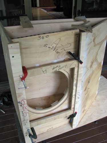
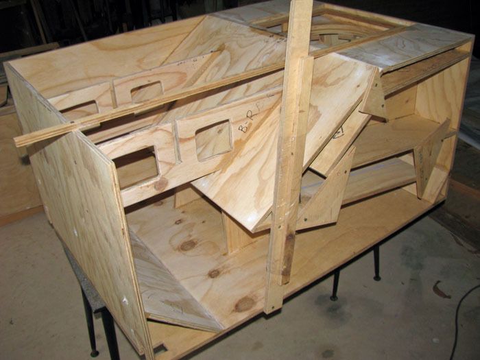
On the side panel it is clearly marked where panel 3 should line up. However, there are no such marks on the top (panel 1). Nor are there lines on panel 3 to show where the reducers make contact.
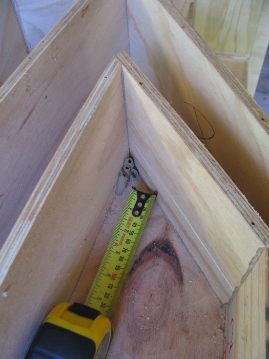
Therefore I placed panel 3 in position and drew lines on the top and panel 3 where the panels and reducers met each other.
I then drilled holes midway between the lines, just like Bill instructs you to do with the side panel.
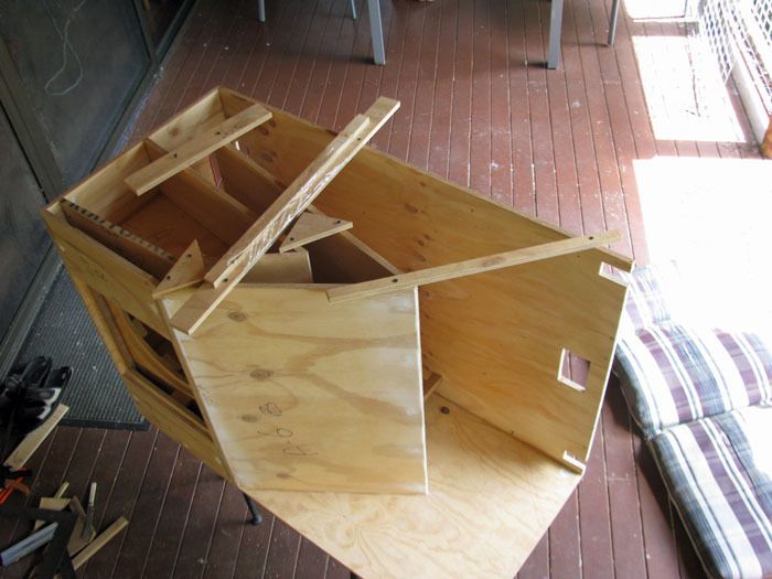
I did a dry assembly and drilled through the holes with my countersunk bit and installed screws. I also adding intermediate holes where needed.
Then assembled again, this time with glue and all the screws.
I couldn't use any of my clamps with this panel, but it didn't matter as it was well supported by the panels it was being glued to.
Image

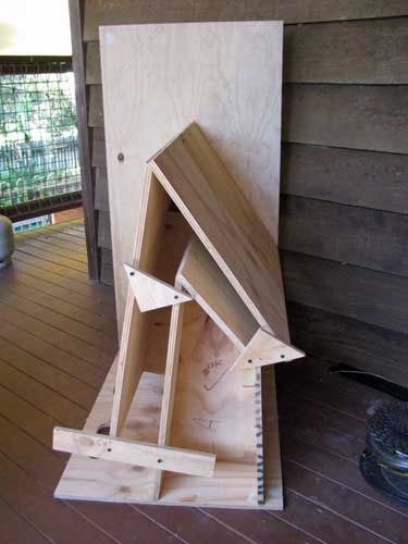
Next was to fit panel 4.

As Bill points out, there are not too many places you can install the screws.
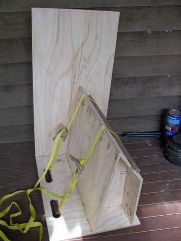
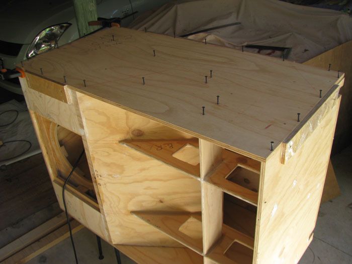
However I decided to buy some straps that are normally used to tie down items in a trailer, etc and clamp the panel into position using the straps.
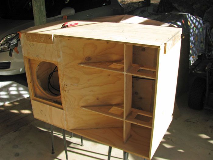
I could still screw the panel to my reducers, and also to the side. So using the method for panel 3 above to locate the screw holes, I added the glue, loosely strapped the panel in position, added the screws, then tightened the straps.
Only have two straps, so the second T39 will have it's panel 4 installed tomorrow. :hyper:
Image

Nordo
Posts: 242
Joined: Thu Aug 25, 2011 4:25 pm
Location: Queensland, Australia

Re: Nordo's Dual T39 Build

#32 Post by Nordo »

Panels 5 and 6
Image
Nothing special to write about.
Dry assembly first with screws; set two screws a couple of mm through the side when gluing to help locate the panel; use scraps at the top to keep panel in line. :wink:

Nordo
Posts: 242
Joined: Thu Aug 25, 2011 4:25 pm
Location: Queensland, Australia

Re: Nordo's Dual T39 Build

#33 Post by Nordo »

Panel 6 Extension and Access Panel Flanges

Image
I found Panel 6 Extension hard to align, even though I used jigs. Problem is that you can't use screws, and I couldn't ensure that the extension was perfectly parallel with the front of the box. Subsequently on one of the boxes the extension is toed in slightly.

Initially, the bottom flanges (cut from panel 3) were too big. But when ripping them back to size, the offcut gave me two perfect pieces for the top flanges.
Also, my boxes are so wide that by cutting one of the panel 3 offcuts in half, I had two bottom flanges of the correct length. So the remaining panel 3 offcut will be used for small braces, etc.

When cutting the side flanges, I took my own measurements. Which was just as well as they were a few mm smaller on one of the boxes.
Before gluing these flanges, I located them in position and marked on them where they contacted the panels and the other flanges. This showed me exactly where to place the glue. Also mark which edge of the flange is "UP" and what will be the front of the flange. I found this made it very easy to place the flange correctly after I had added the glue to the marked areas.

And another thing you MUST do before adding a part to the box - don't forget to trim back any dry excess glue that could upset the alignment of the next part. In my case, the excess glue from the top and bottom flanges would have interfered with the snug fit of the side flanges to these flanges. :wink:
Also fill in any holes as you go. As once assembled, you may not be able to get to some of them.

Note in the photo that I have left the scraps of ply in place that hold the panels in alignment. I will keep them there until the last minute before I close the box up with the second side.

Nordo
Posts: 242
Joined: Thu Aug 25, 2011 4:25 pm
Location: Queensland, Australia

Re: Nordo's Dual T39 Build

#34 Post by Nordo »

Panels 7, 8 and 9 (and associated braces)
Image
Almost every panel I install now has to be individually measured as, for one reason or another, my dimensions don't perfectly match Bill's dimensions. :?
The small little braces supporting the baffle flanges each had to be measured, cut, trimmed, trimmed again, before finally being glued into place. The same for the braces between the rear panel (8) and the internal panel 5.

When installing panel 8, I first thought that my boxes were out of square. Then I realised that the panel 8s, as well as other parts of the box were warped.
Using a straight edge, I established which was the concave face of the offending panel(s), and wiped that face with a wet rag. This worked very well. So well, in fact, that I had to wet the other face on one panel that had started to warp the other way. :oops:

When adding panel 9, I had to locate it in a slightly different position, as I had incorrectly located the hand-holds in the top (panel 1). Instead of cutting the sides of panel 9 at 45 deg, I had to cut one side at 32.5 deg, and the other at 57.5deg. The second cut requiring some work with a planer to achieve the correct angle.
Bit of a fiddle, but got them to fit in the end.
The photo was taken before I had added panel 9.

User avatar
LelandCrooks
Posts: 7244
Joined: Thu May 04, 2006 9:36 am
Location: Midwest/Kansas/Speaker Nirvana
Contact:

Re: Nordo's Dual T39 Build

#35 Post by LelandCrooks »

The joys of anything other than Baltic birch. Nice recovery.
If it's too loud, you're even older than me! Like me.
http://www.speakerhardware.com

Nordo
Posts: 242
Joined: Thu Aug 25, 2011 4:25 pm
Location: Queensland, Australia

Re: Nordo's Dual T39 Build

#36 Post by Nordo »

LelandCrooks wrote:The joys of anything other than Baltic birch. Nice recovery.
"Beggars can't be choosers". :oops:
Leland,
Can you confirm the following screws from your T39 kit (with Lab12, Speakon Deep Dish, Chevron corners, two 2 1/2 castors)
The order was placed in April, 2014 :-

30mm countersunk - general ply assembly
38mm socket head - Lab12 installation
20mm cuphead - Castors
12mm countersunk - Chevron corners

I can see the Speakon deep dish screws are in the electrical connection bag. :wink:

BTW, great kit. All quality stuff. Could not want for anything more.
Cheers :clap: :hyper:

User avatar
LelandCrooks
Posts: 7244
Joined: Thu May 04, 2006 9:36 am
Location: Midwest/Kansas/Speaker Nirvana
Contact:

Re: Nordo's Dual T39 Build

#37 Post by LelandCrooks »

Looks right. I don't usually send socket heads though, unless specified. You must have ordered the speaker mount kit with socket head cap screws and hurricanes. The stock kit uses a 1 1/2 (38mm) recex head wood screw.
If it's too loud, you're even older than me! Like me.
http://www.speakerhardware.com

Nordo
Posts: 242
Joined: Thu Aug 25, 2011 4:25 pm
Location: Queensland, Australia

Re: Nordo's Dual T39 Build

#38 Post by Nordo »

LelandCrooks wrote:Looks right. I don't usually send socket heads though, unless specified. You must have ordered the speaker mount kit with socket head cap screws and hurricanes. The stock kit uses a 1 1/2 (38mm) recex head wood screw.
You're right. :oops:
That's what they are - recex. They came with a recex bit for the drill. (And there are no hurricanes).

Nordo
Posts: 242
Joined: Thu Aug 25, 2011 4:25 pm
Location: Queensland, Australia

Re: Nordo's Dual T39 Build

#39 Post by Nordo »

Panels 10 (bottom) and 11.
Panel 10 was added, using a W brace towards the open side to ensure the panel was square. I also added a piece of offcut to hold the free front edge of panel 10 in the correct position - measure from the top of the box to the bottom and ensure the front edge of panel 10 is a uniform distance from the top panel (panel 1).
There was a slight warp which the W brace and the piece of offcut corrected. I then rubbed a wet cloth on the concave side so that when I took the braces off, the panel would stay square.

Before adding panel 11, don't forget to drill the hole for the cable from the driver to the NL4 plugs.
I drilled the hole in the rear of panel 3 at the same time.
Before gluing panel 11 in place I marked where it should be located on panels 8 and 10. I also predrilled holes to clamp it in place.

Front Braces
After cutting out the vertical and horizontal front braces, I spent quite a bit of time rounding the edges.
I initially used an electric planer and a round file (found the round "second cut" file better than the electric planer).
I then finished off with sand paper.

Before I glued the braces into position, I sanded down all the surfaces in the throat (panels 6,8, 10 & 11, the side, and the braces).
Much easier to do it before the braces are in place.
I had an old cheap orbital sander which was perfect for the job, and will be perfect for sanding all the outside surfaces before painting.

I dry-fitted the vertical braces, trimming the tapered edge until they both were a good fit AND were equi-distant from the front edge of panel 10. This is to ensure that the horizontal brace will be properly aligned.
I screwed them into place. Then removed the screws, added the glue and re-attached the screws.
Note on the photo the piece of offcut used to hold panel 10 in the correct location while fitting the vertical braces. 8)
Image

:hyper: The more you get into the construction, the more each box (I'm building two) will develop their own slightly different dimensions.
Therefore always keep the two builds separate (I call mine A and B), and use the dimensions given in the plan and the model as approximate, and finalise the dimensions using your own measurements of your construction. :wink:

Nordo
Posts: 242
Joined: Thu Aug 25, 2011 4:25 pm
Location: Queensland, Australia

Re: Nordo's Dual T39 Build

#40 Post by Nordo »

Horizontal Throat Brace
Dry fitted the horizontal brace to the two vertical braces. Added a little bit of packing inside one of the slots in a vertical brace to ensure the horizontal brace was properly aligned. Glued the brace into position and screwed the end of the brace of the side panel.

Preparing for the Second Side
First job was to sand/plane all the edges of the cabinet that will make contact with the second side, using a straight edge to check your work.
It doesn't have to be perfect as you will be using plenty of glue and of course, the glue expands.
Second job was to thoroughly clean all the internal sides, channels, braces, corners, etc. This is your last chance before the cabinet is sealed off.
In Queensland we have mud wasps who love to make mud nests in narrow dark places (see the photo). I hope the ones I saw were the only nests that had been built inside the T39s. :fingers:
Image

Added guides wrapped in film to all the external panels, then put the second side into place. The guides hold the side snug in place. However the rear panel and the top were slight concave, but some side screws will pull those into position.
Also noticed that one of my cabinets was not truly square, but I will pull it into alignment with clamps and the screws.

Marked the alignment of the inside panels onto the second side. Could only mark the location of panels 5 and 6, and the horizontal throat brace. But this should give me enough screws to pull the side firmly against all the internal panels.
Offset the lines 6mm to give me the screw locations and drilled the holes for the screws (Similar to the holes you drill in the first side).
BTW, regarding the original holes I drilled when I sandwiched the two sides together (way back at the start of the construction), some were still in good alignment, but some were a fair way off (5-10mm).
I then sat the side in position on the cabinet and drilled and countersunk all holes through the side into the internal panels using the new locations. Then drilled and countersunk holes around all the edges of the side.
Image
Installing the Second side
This is when the T39 cabinet finally looks like a cabinet. :hyper:

Added plenty of glue and fitted the side into place. The guides around the edges keeping the side in alignment while I screwed all the screws home.
Regarding the concave panels, before installing the main screws, I installed the horizontal screws through the guides and into the side, whilst pushing down on the side to make sure it was firmly against the panel. It may be a bit confusing, but if you have a concave panel, you will soon realise what to do. :)
Image
Last edited by Nordo on Wed Dec 30, 2015 2:52 am, edited 3 times in total.

ctmullins
Posts: 195
Joined: Thu May 13, 2010 9:05 am
Location: MS Coast

Re: Nordo's Dual T39 Build

#41 Post by ctmullins »

Thank you Nordo, for building the same cabinet as I am, a few steps ahead of where I am, and sharing your detailed build diary. Helps me a heap! Looking great brother. :cowboy:
-todd

5 and 8 string bass | SansAmp | Crown | 2 x J110
2 x W8 panel-mount
2 x T39 24" 3012LF
4 x OT12 2512 melded (finally done!)

Grant Bunter
Posts: 6915
Joined: Mon Nov 28, 2011 11:12 am
Location: Ilfracombe Queensland Australia
Contact:

Re: Nordo's Dual T39 Build

#42 Post by Grant Bunter »

Nordo,
Great looking build!
Very good to see a max width cab.

I'm curious, what's the spacing between the front braces?
Is it an optical illusion or is the space in the middle wider?
Built:
DR 250: x 2 melded array, 2x CD horn, March 2012 plans.
T39's: 4 x 20" KL3010LF , 2 x 28" 3012LF.
WH8: x 6 with melded array wired series/parallel.
Bunter's Audio and Lighting "like"s would be most appreciated...

Nordo
Posts: 242
Joined: Thu Aug 25, 2011 4:25 pm
Location: Queensland, Australia

Re: Nordo's Dual T39 Build

#43 Post by Nordo »

ctmullins wrote:Thank you Nordo, for building the same cabinet as I am, a few steps ahead of where I am, and sharing your detailed build diary. Helps me a heap! Looking great brother. :cowboy:
Hi Todd
I'm trying to record anything I learnt along the way that was not in Bill's instructions, or evident from the Sketchup model.

One thing I forgot to mention was that when I was cleaning and vacuuming out each cabinet before I installed the second side, I ripped my arms about a bit on the points of the screws that had been used to hold the guides in position. :cussing:

Nordo
Posts: 242
Joined: Thu Aug 25, 2011 4:25 pm
Location: Queensland, Australia

Re: Nordo's Dual T39 Build

#44 Post by Nordo »

Grant Bunter wrote:Nordo,
Great looking build!
Very good to see a max width cab.

I'm curious, what's the spacing between the front braces?
Is it an optical illusion or is the space in the middle wider?
Hi Grant
How's the weather?

Yes, the vertical braces are offset.
Panel 6 already has a centre brace between it and panel 4. So I thought I would move the throat braces away from the centre location a bit.
In hindsight I can now see that this may not brace panel 10 quite as well, but hopefully it shouldn't be a problem.

Another thing I have with bracing panels is that I believe that a "centre" brace shouldn't be exactly at the centre point. This would place the brace at a node, making the brace ineffective for harmonics. Offsetting by, say 15%, should help to reduce this possible problem (I think I did for the brace between panels 6 and 4 :confused: ).
I might be making a mountain out of a molehill. :noob:

BTW, the spacing between the vertical braces is 318mm c/c. Which makes the centre spacing about 46% of the throat; leaving 27% from each brace to the side.

Grant Bunter
Posts: 6915
Joined: Mon Nov 28, 2011 11:12 am
Location: Ilfracombe Queensland Australia
Contact:

Re: Nordo's Dual T39 Build

#45 Post by Grant Bunter »

Nordo wrote: Hi Grant
How's the weather?

Yes, the vertical braces are offset.
Panel 6 already has a centre brace between it and panel 4. So I thought I would move the throat braces away from the centre location a bit.
In hindsight I can now see that this may not brace panel 10 quite as well, but hopefully it shouldn't be a problem.

Another thing I have with bracing panels is that I believe that a "centre" brace shouldn't be exactly at the centre point. This would place the brace at a node, making the brace ineffective for harmonics. Offsetting by, say 15%, should help to reduce this possible problem (I think I did for the brace between panels 6 and 4 :confused: ).
I might be making a mountain out of a molehill. :noob:

BTW, the spacing between the vertical braces is 318mm c/c. Which makes the centre spacing about 46% of the throat; leaving 27% from each brace to the side.
Hey Nordo,
Weather is, well, not to good.
All the rain we were supposed to get from the monsoonal activity up in the gulf has eventuated to nothing yet, for us. Predictions are 15 to 100mm over the next four days.
So basically it's hot, windy, dusty and humid lol.

I hope we are referring to the same thing, the mouth braces, but I guess it applies to all braces.
Ok, horns pretty much eliminate harmonics, so that's not an issue, and the same can be said about nodes.
Panel vibration however is a problem.
It may not be able to be felt by hand, but if it's there, it robs you of output, around 3dB IIRC.

It should say in your plans that nominal bracing width is 6 to 9".
So for the mouth braces, with a 27" wide panel that should mean exactly 9" from each panel edge should be a line, being the centre for that brace, and the measurement from brace to brace centre to centre would also be exactly 9". Sorry about the imperial measurements, but 9 x 3 = 27 lol, so it's a great example.

9" is 228.6mm, so your bracing space of 318mm is in the order of 75mm to wide. I hope it's not going to display itself as a problem for you.

It makes sense to, and says to in the plans, offset braces where they double up, eg panel 2/5, 5/8.
When I built mine (for other than the mouth braces), I simply drew the line, then offset the brace by the thickness of the material so I could get a screw into either side...
Built:
DR 250: x 2 melded array, 2x CD horn, March 2012 plans.
T39's: 4 x 20" KL3010LF , 2 x 28" 3012LF.
WH8: x 6 with melded array wired series/parallel.
Bunter's Audio and Lighting "like"s would be most appreciated...

Post Reply