Lying in bed last night (where I do my best thinking), I suddenly thought I had marked up the sides incorrectly.
This is marking up the locations of the internal panels onto the inner faces of the side panels as per pages 4 and 5.
The first 5 lines form two "V" shapes. Then you add 12mm offsets to these lines per per Bill's instruction "Parallel lines are drawn 1/2 inch to the outside of the first five lines per diagram 4".
I had drawn the parallel lines below each "V", i.e. toward the bottom of the side panel.
It suddenly occurred to me that by ". . .outside of the first 5 lines. . .", Bill had meant that the lower "V" should be offset toward the bottom of the side panel, and the upper "V" should be offset toward the top of the side panel.
However, by measuring the Sketchup model between the bottom point of each "V", then checking against my marked sides, I confirmed that I had offset in the correct direction.
I'm mentioning this in case someone else mis-understands Bill's instruction regarding offsetting the first 5 lines.
Nordo's Dual T39 Build
Re: Nordo's Dual T39 Build
I had similar concerns when marking up the sides. I found that diagram 3 on page 5 of the plans to be most helpful. On that diagram, you can see that the unconnected lines are the the parallel lines that have been added toward the bottom. The Sketchup model is a good confirmation, but since I am a bit ahead of you in my build (at page 13 of the plans), I can confirm that this is correct. The panels are fitting together properly when cut to the specified dimensions/angles.
4 x T39 - 20" - 3012LF (Built 2)
4 x OT12 - 2512 - Melded/D220Ti
1 x TAT - GTO804
4 x OT12 - 2512 - Melded/D220Ti
1 x TAT - GTO804
-
Bill Fitzmaurice

- Site Admin
- Posts: 28647
- Joined: Tue May 02, 2006 5:59 pm
Re: Nordo's Dual T39 Build
This is why the Sketchup includes the side with the panel joint locations shown with no panels blocking the view. You can measure the line positions on the model, especially helpful if you need metric dimensions.
Re: Nordo's Dual T39 Build
Hi Guys
I don't know where to post this, so I'm posting it here.
I started this thread. I've subscribed to it, I've bookmarked it, but I am not getting notifications of when people are posting on this thread!!!!
I have previously subscribed to other threads and would receive emails of postings on those threads.
But, for some reason, I can't seem to set up this topic so that I get immediate email notifications of postings.
Has anyone got any ideas what's happening and what to do to fix it?
Re: Nordo's Dual T39 Build
Sorry that my project has stalled over the last few months.
Had a lot going on, and my personal interests had to take a back seat.
However, hopefully I now have a bit more "self" time and I can start moving again with my T39s.
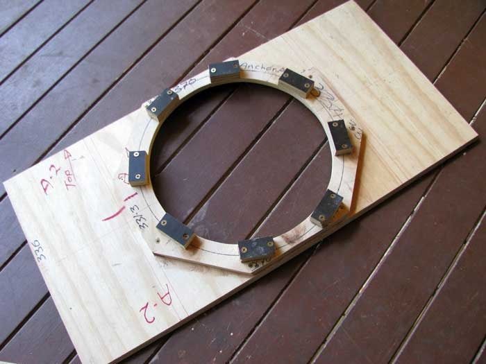
I have now built my baffles, complete with anchors and retention blocks as I am using Lab12s. Note that the retention blocks (black) are from some 17mm hardwood formply I had lying around.
Had a lot going on, and my personal interests had to take a back seat.
However, hopefully I now have a bit more "self" time and I can start moving again with my T39s.
I have now built my baffles, complete with anchors and retention blocks as I am using Lab12s. Note that the retention blocks (black) are from some 17mm hardwood formply I had lying around.
Last edited by Nordo on Thu Oct 01, 2015 5:30 pm, edited 1 time in total.
Re: Nordo's Dual T39 Build
I then cut out the reducers.
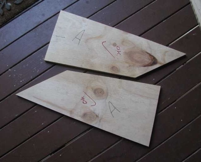
I had a problem with the reducers.
When I laid a reducer on my side panel, which was all marked up with the position of the internal panels, the reducer didn't match the corresponding lines on the panel.
I checked all measurements 3 or 4 times, but everything matched the instructions.
I then sat down and using the measurements of the internal panels layout on the side, I calculated the correct cut-out dimensions for the reducers.
I now believe that in Bill's instructions and cutting dimensions for the reducers, the offset dimension of 2 7/16" should be 2 9/16" (65.1mm). YMMV
My next step is to take a deep breath and start gluing. However I will definitely be doing a dry assembly before each gluing session.
I'll be gluing the reducers to the baffles, then the baffles with the top (No.1) to the marked up side.
Re: Nordo's Dual T39 Build
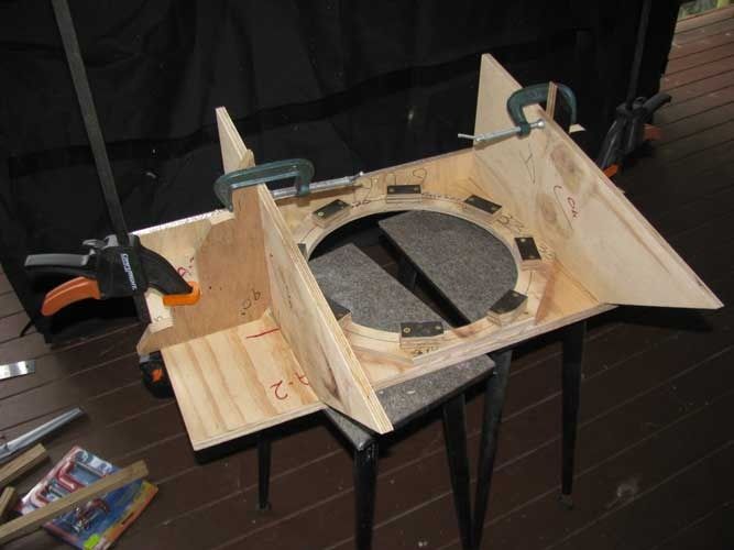
Added the reducers to the baffles.
A copy of things to note.
1. I marked the inside face of the baffle with twin lines, the same as you mark the inside face of the side that you glue the internal panels to. I don't think it is wise to trust the ends of the anchor plate as being square. I also marked the centreline of the reducers on the outside face of the baffle to locate the screws.
2. I did a "dry" assembly. Each reducer is fixed with 4 screws. I added the end screws first, making sure the reducer lined up exactly with my lines, then added the other screws. The reason for the dry assembly is that when you add the glue, the half-installed screws will act as locating pins. Also trying to locate the reducer on the lines without the pre-made screw holes is impossible as the glue ouses out and covers the lines.
This problem with glue ouse covering alignment lines will be common to all through the assembly.
3. Don't forget the gladwrap on the end jig (I nearly did ).
).
4. Due to the size of my W clamps, I had to cut an extra notch for the clamp.
A copy of things to note.
1. I marked the inside face of the baffle with twin lines, the same as you mark the inside face of the side that you glue the internal panels to. I don't think it is wise to trust the ends of the anchor plate as being square. I also marked the centreline of the reducers on the outside face of the baffle to locate the screws.
2. I did a "dry" assembly. Each reducer is fixed with 4 screws. I added the end screws first, making sure the reducer lined up exactly with my lines, then added the other screws. The reason for the dry assembly is that when you add the glue, the half-installed screws will act as locating pins. Also trying to locate the reducer on the lines without the pre-made screw holes is impossible as the glue ouses out and covers the lines.
This problem with glue ouse covering alignment lines will be common to all through the assembly.
3. Don't forget the gladwrap on the end jig (I nearly did
4. Due to the size of my W clamps, I had to cut an extra notch for the clamp.
Re: Nordo's Dual T39 Build
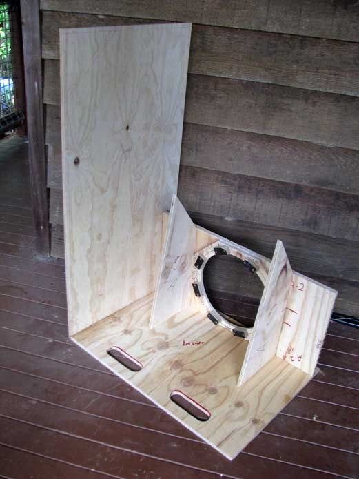
Now glued Top (1) and Baffle (2) with reducers to the marked up side.
No great words of advice - except dry assemble everything first.
It really is a pain in the butt with only one drill, but it's worth it.
I was going to do this part of the assembly in one hit, but after I had added the top to the side, I realized that it was best to leave the baffle to the next day.
As soon as I have added the adhesive, I immediately seal off the end of the nozzle with some tape. If you leave it for more than a couple of days, even with the tape in place, the adhesive will start to dry in the nozzle, and you need something long and thin to poke into the nozzle to break through the drying adhesive.
Has anyone any better suggestions for sealing off the open end of the nozzle?

-
Bruce Weldy
- Posts: 8325
- Joined: Fri Nov 27, 2009 11:37 am
- Location: New Braunfels, TX
Re: Nordo's Dual T39 Build
Nordo wrote:
Has anyone any better suggestions for sealing off the open end of the nozzle?
Yep...
This....
6 - T39 3012LF
4 - OT12 2512
1 - T24
1 - SLA Pro
2 - XF210
"A system with a few knobs set up by someone who knows what they are doing is always better than one with a lot of knobs set up by someone who doesn't."
-
Bill Fitzmaurice
- Site Admin
- Posts: 28647
- Joined: Tue May 02, 2006 5:59 pm
Re: Nordo's Dual T39 Build
The potential for double entendres is huge.
Re: Nordo's Dual T39 Build
it should be placed next to this:Bill Fitzmaurice wrote:The potential for double entendres is huge.

BFM builds:
XF212
T24 BP102 24"
2x SLA's 6-5" mids, 9- gt-302's
2x AT 14" MCM 55-2421
TrT 5" MCM 55-2421
AT 18" JBL GTO804
2x OT12 flat array
2x SLA Pro 2-Alpha 6's 2-Goldwoods
2x T39 24" 3012lf
Simplex 10 BP102
XF212
T24 BP102 24"
2x SLA's 6-5" mids, 9- gt-302's
2x AT 14" MCM 55-2421
TrT 5" MCM 55-2421
AT 18" JBL GTO804
2x OT12 flat array
2x SLA Pro 2-Alpha 6's 2-Goldwoods
2x T39 24" 3012lf
Simplex 10 BP102
Re: Nordo's Dual T39 Build
Mmmmm.
-
Chris_Allen

- Posts: 3355
- Joined: Wed Jul 11, 2007 2:43 pm
- Location: Huddersfield, UK
Re: Nordo's Dual T39 Build
I always think that when building T39/T48s with reducer panels, you could external route the opposing side of the reducer and create a funky little hole. The only purpose would be to confuse people or hold your beer.
Built:
6xDR200, 2xT39, 2xT48, 2xJack110, 1xOmni10.5, 1xAutotuba, 1xT18, 1xSLA Pro, 1xW8, 1xW10
6xDR200, 2xT39, 2xT48, 2xJack110, 1xOmni10.5, 1xAutotuba, 1xT18, 1xSLA Pro, 1xW8, 1xW10
-
David Raehn
- Posts: 676
- Joined: Tue Apr 30, 2013 5:56 pm
- Location: Colonial Beach VA
Re: Nordo's Dual T39 Build
Or you could do one of those cloverleaf-shaped natural handles and give yourself a place to keep speaker cables....
- Attachments
-
BFM rig:
6 OT12
4 T48
4 WH8
Other:
56 box Electrotec LabQ rig
Way too many cables

6 OT12
4 T48
4 WH8
Other:
56 box Electrotec LabQ rig
Way too many cables
-
heavybdrums

- Posts: 366
- Joined: Fri May 22, 2015 3:46 pm
- Contact:
Re: Nordo's Dual T39 Build
Well this is going well and looking good, I'm sure you're enjoying your build, I know I have on these T39's. Just some encouragement; T39's (I have one built and using it) are really awesome sounding, chest thumping, air moving beastsNordo wrote:
Now glued Top (1) and Baffle (2) with reducers to the marked up side.
No great words of advice - except dry assemble everything first.
It really is a pain in the butt with only one drill, but it's worth it.
I was going to do this part of the assembly in one hit, but after I had added the top to the side, I realized that it was best to leave the baffle to the next day.
As soon as I have added the adhesive, I immediately seal off the end of the nozzle with some tape. If you leave it for more than a couple of days, even with the tape in place, the adhesive will start to dry in the nozzle, and you need something long and thin to poke into the nozzle to break through the drying adhesive.
Has anyone any better suggestions for sealing off the open end of the nozzle?
Have Fun!!
4x WH8 delta pro
2x WH10 Deltalite 2510
4x Dr250 Deltalite II 2510
8X Titan 39 3012lf, 28"
4X Tuba 60 W/ lab 15
FB: https://www.facebook.com/sunsoundservices/ likes appreciated
2x WH10 Deltalite 2510
4x Dr250 Deltalite II 2510
8X Titan 39 3012lf, 28"
4X Tuba 60 W/ lab 15
FB: https://www.facebook.com/sunsoundservices/ likes appreciated