How to set up your measurement mics for RTA purposes

EQ guys are using on their cabs/systems. A good starting place if you don't have your own RTA.
Post Reply
Message
Author
User avatar
DAVID_L_PERRY
Posts: 1685
Joined: Mon Jul 10, 2006 7:35 am
Location: UK North west
Contact:

How to set up your measurement mics for RTA purposes

#1 Post by DAVID_L_PERRY »

I would like others to post how they carry this out

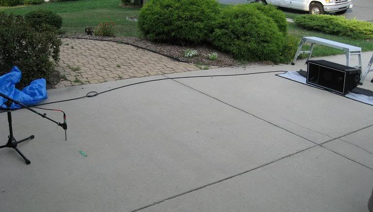
I have read and seen different approaches to mic placement (cabs laid on the ground with the mic pointing straight down 1/2" off the ground). This shows what I am talking about :-
Image

I would like to find out a little more about the 'correct procedure' but here is what has worked very well for me.

To date I have always had the mic on axis roughly at 10-12 feet away from the cab being measured

This is the method I use for the Behringer DEQ and measurement mic:-

1) Set up your PA system, only plug in one side of your tops.

2) Place the measurement microphone on axis pointing at the top cab roughly 10-12 feet away from the cab to allow the elements to integrate

3) Reset your eq on the DEQ flat

4) Press the RTA button and the screen will say 'edit target curve'. The unit will show you the 31band eq but only down to 100hz - It should be completely flat - don't change this curve

5) follow the on-screen instructions and the unit should then start its process (you may have to press 'start') No need to have the pink noise at war volume, just loud enough to get over the ambient room level. You adjust the level of the pink noise by turning the large central control.

6) Press the page button to view in real time the adjustment being made to the graphic. At first the unit will start with massive changes by grabbing 3-4 eq sliders at a time and making big adjustment, keep watching it and it will start to re-adjust the eq and then start to adjust things less and less. Once it looks as though it is only making tiny adjustments you can press 'done'.

7) press the GEQ button and you can see the adjustments that have been made. Every time I have done this there have been several single freq's that have been boosted/cut massively. I will tend to smooth these out as I make an assumption that they could be room related modes

8 ) Plug your subs and tops back in. Play some music through the system and try swapping the polarity of your subs or tops over. One will result in stronger bass end at the crossover freq. I always check this out at each and every gig as sub placement will dictate how this effects things - typically my subs are inverted

9) Listen to the music with the eq on and then bypassed, you may need to adjust the overall EQ gain by a couple of DB's to make up for overall eq loss due to cuts being made in the eq shape - I simply listen for the volume difference and adjust to suit.

10) Don't rely on the RTA result being the complete answer.....you may find that too much has been cut from the lower mids for example...adjust it to suit, but in my experience it has always resulted in a far, far better sound.

Hope that helps a little
Dave

User avatar
Bill Fitzmaurice
Site Admin
Posts: 28916
Joined: Tue May 02, 2006 5:59 pm

#2 Post by Bill Fitzmaurice »

Doing it as in the picture is fine with subs, and with mains up to 200-300 Hz, giving a reasonable approximation of half-space anechoic. For the higher frequencies lift the cab 5 feet or so above the ground and measure on-axis, over grass, not concrete, so reflections won't corrupt the result. This is technically free-space, but above the baffle step frequency it's half-space anyway. Combine the two results. In the transition zone where the baffle step may not be fully overcome, 300-400 Hz or so, use the higher of the two results. This gives you the information needed to set the system to flat outdoors, but of course once you take it indoors the room changes everything and you have to adjust accordingly.

User avatar
DAVID_L_PERRY
Posts: 1685
Joined: Mon Jul 10, 2006 7:35 am
Location: UK North west
Contact:

#3 Post by DAVID_L_PERRY »

Thanks Bill
So is it better to do the measurements in two steps...
1) on the ground to establish eq upto 300hz as shown in the photo
2) off the ground for 300hz and above

Or is it ok to do all of the measurement off the ground...

I struggle to understand how it makes sense to measure the top on the ground (half space) when it will never be in that situation. Whats the main reasons for this.

Dave

User avatar
Bill Fitzmaurice
Site Admin
Posts: 28916
Joined: Tue May 02, 2006 5:59 pm

#4 Post by Bill Fitzmaurice »

DAVID_L_PERRY wrote:Thanks Bill
So is it better to do the measurements in two steps...
1) on the ground to establish eq upto 300hz as shown in the photo
2) off the ground for 300hz and above

Or is it ok to do all of the measurement off the ground...

I struggle to understand how it makes sense to measure the top on the ground (half space) when it will never be in that situation. Whats the main reasons for this.

Dave
Standard loudspeaker measurements are made in half-space, which in an anechoic chamber is accomplished by having the speaker walled in. Outdoors you can duplicate that by digging a hole in the ground, placing the speaker in the hole facing up, the baffle flush with the ground. Backfill the hole, and measure with the mic suspended on a boom above the cab. Not convenient. The alternative is to measure below the baffle step frequency (1 wavelength across) where radiation is omnidirectional with the ground-plane method. This approximates half-space. Above the baffle step the cab is in half-space already, radiating hemispherically, so a ground plane measurement is now quarter-space. To return it to half-space the cab is elevated at least a wavelength.

User avatar
James R
Posts: 681
Joined: Mon Jul 31, 2006 7:49 pm
Location: Upstate NY

Re:

#5 Post by James R »

Bill Fitzmaurice wrote:Doing it as in the picture is fine with subs, and with mains up to 200-300 Hz, giving a reasonable approximation of half-space anechoic. For the higher frequencies lift the cab 5 feet or so above the ground and measure on-axis, over grass, not concrete, so reflections won't corrupt the result. This is technically free-space, but above the baffle step frequency it's half-space anyway. Combine the two results. In the transition zone where the baffle step may not be fully overcome, 300-400 Hz or so, use the higher of the two results. This gives you the information needed to set the system to flat outdoors, but of course once you take it indoors the room changes everything and you have to adjust accordingly.
Bill,
So I should measure my subs on concrete as ( Dave Perry had pictured in his post )and the tops over grass correct? just making sure I'm going to give it a go saturday.

thanks,
Jim

Edit: Also wich would be better, read a single sub or all of them?
" Everyone Has a Photographic Memory, Just Not Everyone Has Film In The Camera"


4 x T48 24.5" 3015LF
8 x 112 Otops


NEXT 2 x DR280's

WB
Posts: 1745
Joined: Sat May 13, 2006 3:06 pm
Location: Ontario. Yours To Discover

Re: How to set up your measurement mics for RTA purposes

#6 Post by WB »

I can't see the house in the picture, but I'm guessing the the garage door and house is nearby, which could cause some spikes and dips in the readings. I like to keep well away from large surfaces such as buildings.
Tomorrow I'm going to stop procrastinating - WB

User avatar
Bill Fitzmaurice
Site Admin
Posts: 28916
Joined: Tue May 02, 2006 5:59 pm

Re: How to set up your measurement mics for RTA purposes

#7 Post by Bill Fitzmaurice »

WB wrote: I like to keep well away from large surfaces such as buildings.
At least 2 wavelengths is best. At 40 Hz that's 56 feet, so it isn't always practical.
Edit: Also wich would be better, read a single sub or all of them?
What's the intent? Keep in mind that perfect measurements made outdoors are nice to confirm everything works right, but as soon as you move indoors the results are anecdotal. In a room what counts how getting it to sound good, not to get flat response. The two are seldom the same. RTAs are most useful in identifying room modes that need taming, but that's it.

User avatar
James R
Posts: 681
Joined: Mon Jul 31, 2006 7:49 pm
Location: Upstate NY

Re: How to set up your measurement mics for RTA purposes

#8 Post by James R »

Bill,
When I made this statement
Edit: Also wich would be better, read a single sub or all of them?
I meant as you were running, say 2 a side or 4 clustered, so should the measurement include this, the intent was to achieve a base reading. Then when indoors tweak as needed,
but judging by what has been said a single sub should do.

Thanks,
Jim
" Everyone Has a Photographic Memory, Just Not Everyone Has Film In The Camera"


4 x T48 24.5" 3015LF
8 x 112 Otops


NEXT 2 x DR280's

User avatar
Bill Fitzmaurice
Site Admin
Posts: 28916
Joined: Tue May 02, 2006 5:59 pm

Re: How to set up your measurement mics for RTA purposes

#9 Post by Bill Fitzmaurice »

James R wrote:Bill,
When I made this statement
Edit: Also wich would be better, read a single sub or all of them?
I meant as you were running, say 2 a side or 4 clustered, so should the measurement include this, the intent was to achieve a base reading. Then when indoors tweak as needed,
but judging by what has been said a single sub should do.

Thanks,
Jim
Response changes as more cabs are added, so you would want to measure them all. And while at it measure with 2 per side and see why that's seldom a good idea. :conf:

User avatar
James R
Posts: 681
Joined: Mon Jul 31, 2006 7:49 pm
Location: Upstate NY

Re: How to set up your measurement mics for RTA purposes

#10 Post by James R »

Bill Fitzmaurice wrote:
James R wrote:Bill,
When I made this statement
Edit: Also wich would be better, read a single sub or all of them?
I meant as you were running, say 2 a side or 4 clustered, so should the measurement include this, the intent was to achieve a base reading. Then when indoors tweak as needed,
but judging by what has been said a single sub should do.

Thanks,
Jim
Response changes as more cabs are added, so you would want to measure them all. And while at it measure with 2 per side and see why that's seldom a good idea. :conf:
Yes I know boundary load the whenever possible, or make sure they're at least a wave length away from each other. But those situations where I cannot do that ( sucks ) due to floor space etc.
I was just trying to cover all the bases and maybe save them as presets in the dbx drpa I already have for the different situations.But plans changed for sat got a gig now, but this place I get to stack them all together :D

Thanks,
Jim
" Everyone Has a Photographic Memory, Just Not Everyone Has Film In The Camera"


4 x T48 24.5" 3015LF
8 x 112 Otops


NEXT 2 x DR280's

bgavin
Posts: 5738
Joined: Thu May 04, 2006 10:58 am
Location: Sacramento, Moderator/Licensed BF Builder
Contact:

Re: How to set up your measurement mics for RTA purposes

#11 Post by bgavin »

One thing you might consider doing is the 100 watts at 10 meters measurement. This produces the same relative plot as 1w/1m, but removes any potential for artificial inflation of the numbers from baffle effects or Doppler distortion. 100w/10m is also a more realistic measurement of real-world performance.

BTW, commercial bass cabs are pretty wimpy when measured outdoors at 100w/10m. The distance filters out much of the Doppler distortion, so what is left (not much) is what the box actually produces.
My biggest worry is that when I'm dead and gone, my wife will sell my toys for what I said I paid for them.

bgavin
Posts: 5738
Joined: Thu May 04, 2006 10:58 am
Location: Sacramento, Moderator/Licensed BF Builder
Contact:

Re:

#12 Post by bgavin »

DAVID_L_PERRY wrote:I struggle to understand how it makes sense to measure the top on the ground (half space) when it will never be in that situation. Whats the main reasons for this.
The reason for this is angular error. Ground plane measurements include the real and reflected images of the produced sound. Joe D'Appolito explains the math in his book for those who are interested.

A right triangle is formed from the speaker center, the ground, and the microphone. The higher the speaker off the ground, the more severe is the angle, and the longer the hypotenuse. The reflected image creates the same triangle which is why the mic is in the "center". The ground plane is the common side of the two triangles. The center line places the mic equidistant from the real and reflected sound sources.

If the mic was not centered, it would measure cancellations occuring when the direct tone arrives at a different time than the reflected tone, as a result of different distances. The higher the frequency, the more problematic this becomes. This is why you shift to free space (elevated) measurements for high frequency devices.

For tops, the driver triangle height is large compared to small wave lengths. Tops are too far above the ground for boundary loading, so they run in free space for the most part. This is not the case for subs. Most subs run on the ground where the boundary reflected image is significant to the sub output.
My biggest worry is that when I'm dead and gone, my wife will sell my toys for what I said I paid for them.

User avatar
Bill Fitzmaurice
Site Admin
Posts: 28916
Joined: Tue May 02, 2006 5:59 pm

Re: Re:

#13 Post by Bill Fitzmaurice »

bgavin wrote:This is not the case for subs. Most subs run on the ground where the boundary reflected image is significant to the sub output.
Ideally a sub, or any cab, is measured outdoors, facing up, in a pit backfilled so that the groundplane and baffle are the same, with the mic suspended above it. That's impractical of course, so to approximate half-space the cab is measured with the mic at ground level. Where the wavelengths are long enough that the refection path off the ground is too short in comparison with a wavelength to affect the result it is for all intents and purposes a half-space result. But if the reflection path approaches 1/4 wavelength the result isn't half-space, so the cab must be lifted high enough above the ground to render the reflection out of the equation. OTOH with large prosound cabs you can still get a halfspace result when measured elevated, as when the cab's face dimension hits 1 wavelength radiation is half-space. In the case of a 22x22 inch DR250, for instance, that occurs at 600Hz. So to get a half-space result with DR250 you measure ground plane, taking those results up to 600 Hz, and elevated, taking those results above 600 Hz, and sum the two.

Post Reply